AYK550-UH User’s Manual
118
Start-Up
4025
WAKE-UP DEVIATION
0.0…1000%
0.1
0.0
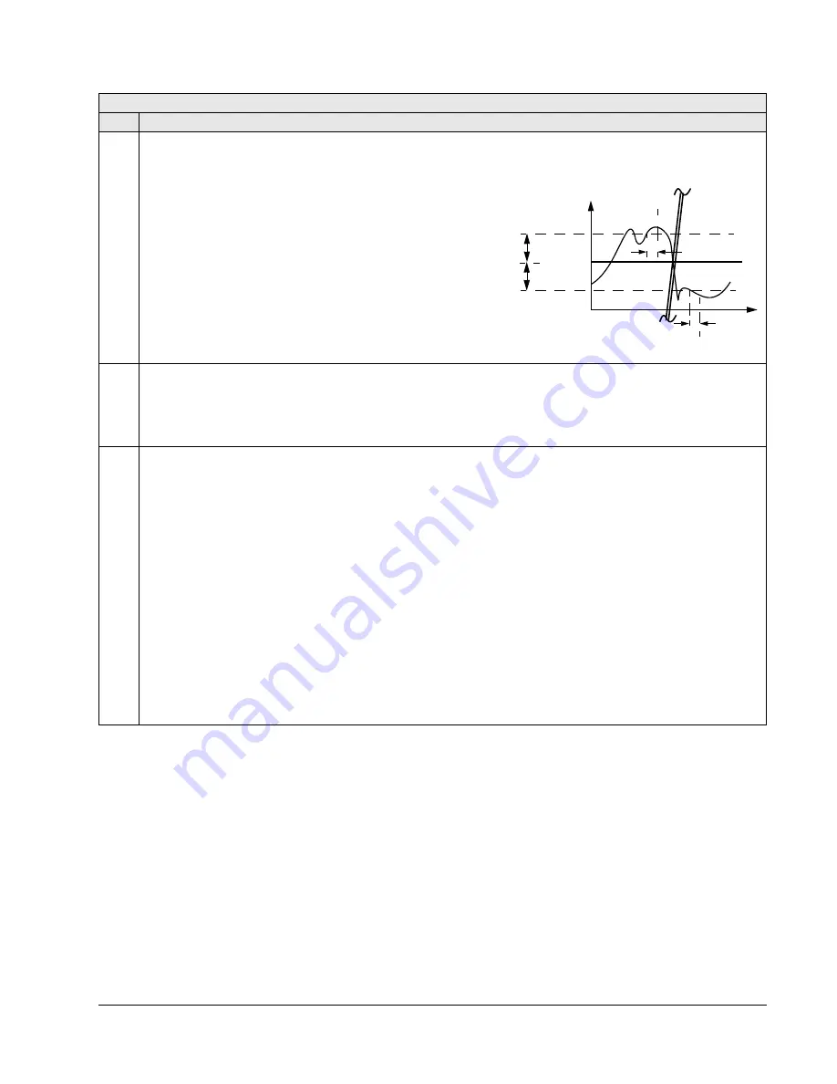
Defines the wake-up deviation – a deviation from the setpoint greater than this value, for at least the time period
4026
WAKE
-
UP
DELAY
, re-starts the PID controller.
• Parameters 4006 and 4007 define the units and scale.
• Parameter 4005 = 0,
Wake-up level = Setpoint – Wake-up deviation.
• Parameter 4005 = 1,
Wake-up level = Se Wake-up deviation.
• Wake-up level can be above or below setpoint.
See figures:
• C = Wake-up level when parameter 4005 = 1
• D = Wake-up level when parameter 4005 = 0
• E = Feedback is above wake-up level and lasts longer than 4026
WAKE
-
UP
DELAY
– PID function wakes up.
• F = Feedback is below wake-up level and lasts longer than 4026
WAKE
-
UP
DELAY
– PID function wakes up.
4026
WAKE-UP DELAY
0.00…60.00 s
0.01 s
0.50 s
Defines the wake-up delay –
a deviation from the setpoint greater than 4025
WAKE
-
UP
DEVIATION
, for at least this time period, re-starts the PID
controller.
• See 4023
PID
SLEEP
LEVEL
above.
4027
PID 1 PARAM SET
-6…11
1
0
Defines how selections are made between PID Set 1 and PID Set 2.
PID parameter set selection. When set 1 is selected, parameters 4001…4026 are used.
When set 2 is selected, parameters 4101…4126 are used.
0 =
SET
1 – PID Set 1 (parameters 4001…4026) is active.
1 =
DI
1 – Defines digital input
DI
1 as the control for PID Set selection.
• Activating the digital input selects PID Set 2.
• De-activating the digital input selects PID Set 1.
2…6 =
DI
2…
DI
6 – Defines digital input
DI
2…
DI
6 as the control for PID Set selection.
• See
DI
1 above.
7 =
SET
2 – PID Set 2 (parameters 4101…4126) is active.
8…11 =
TIMER
1…4 – Defines the Timer as the control for the PID Set selection (Timer de-activated = PID Set 1;
Timer activated = PID Set 2)
See parameter Group 36: Timer Functions.
-1 =
DI
1(
INV
) – Defines an inverted digital input
DI
1 as the control for PID Set selection.
• Activating the digital input selects PID Set 1.
• De-activating the digital input selects PID Set 2.
-2…-6 =
DI
2(
INV
)…
DI
6(
INV
) – Defines an inverted digital input
DI
2…
DI
6 as the control for PID Set selection.
• See
DI
1(
INV
) above.
Group 40: Process PID Set 1
Code Description Range
Resolution
Default
S
P 4025
Setpoint
P 4025
C
D
t
P 4026
E
F
P 4026
Summary of Contents for AYK 550
Page 256: ...D1 AYK550 UH User s Manual Appendix D Appendix D Base Drive Drawing 205662 Drawings Fig 1...
Page 257: ...AYK550 UH User s Manual D2 Appendix D Base Drive w Fused Disconnect Drawing 205648 Fig 2...
Page 258: ...D3 AYK550 UH User s Manual Appendix D Base Drive w Non Fused Disconnect Drawing 205647 Fig 3...


