AYK550-UH User’s Manual
130
Start-Up
8117
NR OF AUX MOT
0…3
1
1
9
Sets the number of auxiliary motors.
• EAYK auxiliary motor requires a relay output, which the drive uses to send start/stop signals.
• The Autochange function, if used, requires an additional relay output for the speed regulated motor.
The following describes the set-up of the required relay outputs.
Relay Outputs
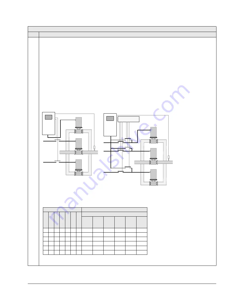
As noted above, eAYK auxiliary motor requires a relay output, which the drive uses to send start/stop signals. The
following describes how the drive keeps track of motors and relays.
• The AYK550 provides relay outputs RO1…RO3.
• An external digital output module can be added to provide relay outputs RO4…RO6.
• Parameters 1401…1403 and 1410…1412 define, respectively, how relays RO1…RO6 are used – the parameter
value 31 PFA defines the relay as used for PFA.
• The AYK550 assigns auxiliary motors to relays in ascending order. If the Autochange function is disabled, the first
auxiliary motor is the one connected to the first relay with a parameter setting = 31 PFA, and so on. If the
Autochange function is used, the assignments rotate. Initially, the speed regulated motor is the one connected to
the first relay with a parameter setting = 31 PFA, the first auxiliary motor is the one connected to the second relay
with a parameter setting = 31 PFA, and so on
• The table below shows the AYK550 PFA motor assignments for some typical settings in the Relay Output
parameters (1401…1403 and 1410…1412), where the settings are either =31 (PFA), or =X (anything but 31), and
where the Autochange function is disabled (8118
AUTOCHNG
INTERV
= 0).
* =One additional relay output for the PFA that is in use.
One motor is in “sleep” when the other is rotating.
Group 81: PFA
Code Description Range
Resolution
Default
S
AYK550
Standard PFA mode
PFA with Autochange mode
AYK550
Relay Logic
Parameter Setting
AYK550 Relay Assignment
1
4
0
1
1
4
0
2
1
4
0
3
1
4
1
0
1
4
1
1
1
4
1
2
8
1
1
7
Autochange Disabled
RO1 RO2 RO3 RO4 RO5 RO6
31 X X X X X 1 Aux. X
X
X
X
X
31 31 X X X X 2 Aux. Aux. X
X
X
X
31 31 31 X X X 3 Aux. Aux. Aux. X
X
X
X 31 31 X X X 2 X
Aux. Aux. X
X
X
X
X
X
31
X
31
2 X X X Aux.
X Aux.
31 31 X X X X 1* Aux.
Aux.
X
X
X
X
Summary of Contents for AYK 550
Page 256: ...D1 AYK550 UH User s Manual Appendix D Appendix D Base Drive Drawing 205662 Drawings Fig 1...
Page 257: ...AYK550 UH User s Manual D2 Appendix D Base Drive w Fused Disconnect Drawing 205648 Fig 2...
Page 258: ...D3 AYK550 UH User s Manual Appendix D Base Drive w Non Fused Disconnect Drawing 205647 Fig 3...


