FORM 100.10-NOM2
47
YORK INTERNATIONAL
Airfoil Wheels
The airfoil wheels can be removed from the side of
the fan housing by removing the side panels. It is pos-
sible to remove the fan wheel through the fan dis-
charge opening.
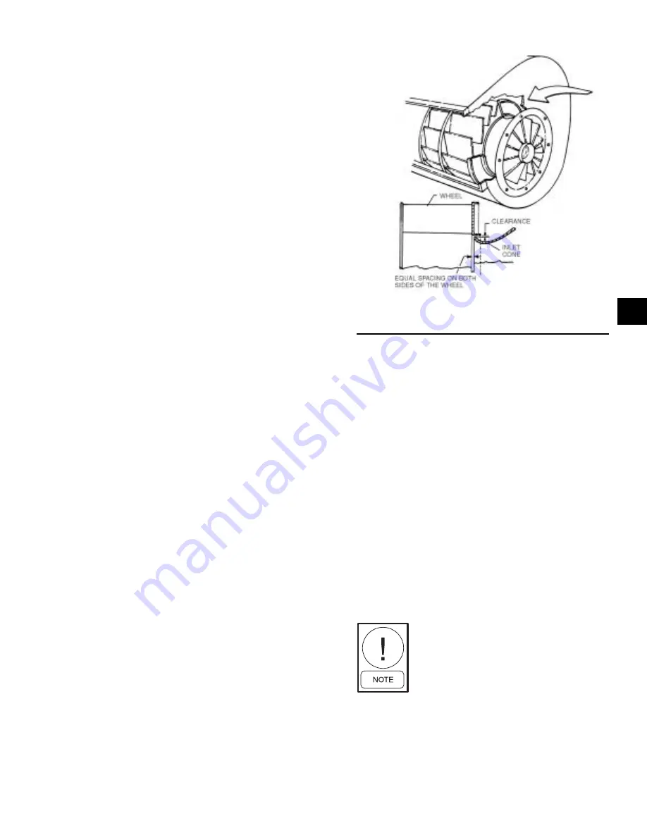
The first step in the removal of the fan wheel is to re-
move the inlet cone from the side of the fan from which
the wheel is to be removed from the unit. If the wheel
is to be removed from the fan discharge, one of the
inlet cones must be removed from the side of the hous-
ing since the cones nest inside the blower wheel. (See
Figure 46) The remaining steps for removing the as-
sembly are the same as those provided in the instruc-
tions for removing the forward curved fans.
Fan Motor
1. Shut off motor power and lock out.
2. Disconnect and tag power wires at motor terminals.
3. Loosen motor brace-to-mounting-rail attaching
bolts.
4. Mark belt as to position. Remove and set aside belts.
5. Remove motor bracket hold down bolts.
6. Remove motor pulley and set aside.
7. Remove motor.
8. Install new motor. Reassemble by reversing steps
1 - 6. Be sure to reinstall multiple belts in their origi-
nal position. Use a complete new set if required.
Do not stretch belts over sheaves. Review the sec-
tions on motor and sheave installation. Sheave align-
ment and belt tensioning discussed previously.
9. Reconnect motor leads and restore power. Check
fan for proper rotation as described in Start-Up
Check List.
Fan Shaft Bearings
General –
When removing and replacing the bearings,
care should be taken to ensure that the area where the
bearings fit on the shaft does not become scored or
damaged. The shaft in this area should be thoroughly
cleaned before the bearing is removed and again be-
fore the new bearing is installed.
Mounting Details –
1. Check the shaft - it should be straight, free of burrs
and full size. Be sure the bearing is not seated on a
worn section of shafting.
FIG. 46 –
AIRFOIL INLET VANE AND CONE
ASSEMBLY
2. Make certain any set screws are not obstructing
the bearing bore.
3. Align the bearing in its housing and slide the bearing
into position on shaft - never hammer the ends of the
inner race. If necessary, use a brass bar or pipe
against the inner race to drift bearing into place –
never hit the housing as bearing damage may result.
Make sure there is lubricant between the bearing
outer ring and the housing.
4. Fasten the bearing housing to the unit mounting sup-
port with hex head cap screws, washers, new lock
washers and hex nuts before securing the bearing
to the shaft. This permits the bearing to align itself
in position along the shaft and eliminates any possi-
bility of cramping loads.
5. Rotate the shaft to make certain it turns freely.
6. Bearings may employ one of several different meth-
ods to lock the bearing to the shaft.
Shaft should be free from burrs. If old
shaft is used, be sure a ball bearing is
not seated on worn section and shaft
is not bent.
There are various degrees of self alignment in bearings
of the same manufacturer. The force required for the
self alignment of the bearings used in YORK manufac-
tured units has been specified and is closely monitored
LD06356
4


