YORK INTERNATIONAL
60
Service
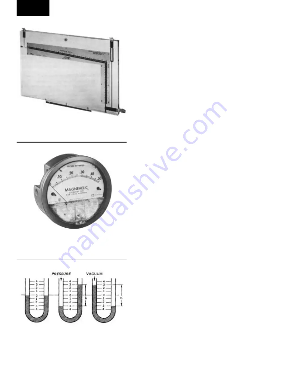
INCLINED MANOMETER
This instrument, also known as a draft gauge, is a simple,
foolproof device, which responds directly to the air pres-
sure exerted against it (transmitted from the Pitot tube),
and reads directly in inches of water. Ranges for these
instruments vary, and the technician should have one or
more instruments to cover the range of 0 to 8 inches of
water. (See Figure 63)
MAGNEHELIC PRESSURE GAUGE
“Magnehelic” is not a generic term but is registered by
Dwyer Instrument Company. The magnehelic gauge is
a diaphragm-operated gage that has several advantages
over a liquid manometer:
1. It need not be leveled to 0 and can be used easily
on a ladder or unlevel surface.
2. When hooked up to the Pitot tube it need not be
purged of air bubbles as the liquid manometer may.
3. There is less chance of parallax error in reading
the dial face.
4. It is easily transported without the chance of losing
the liquid charge. Unless extreme accuracy is re-
quired, this instrument may replace the manometer
for average air conditioning work, and, like the ma-
nometer, is available in a variety of ranges. The dial
is only 4 inches in diameter and therefore has a
limited scale: several instruments are required to
cover the normal ranges encountered in average
air conditioning jobs. (See Figure 64)
“U” TUBE MANOMETER
Pressure is defined as force per unit area - and the best
way to measure air pressure is to balance a column of
liquid of known weight against the air pressure and
measure the height of liquid columns so balanced. The
units of measure commonly used are: inches of mer-
cury (in. Hg), using mercury as the fluid; and inches of
water (in. WG), using water or oil as the fluid.
Instruments employing this principle are called manom-
eters. The simplest form is the basic and well known
U-tube manometers. (See Figure 65) This device indi-
cates the difference between two pressures or between
a single pressure and atmosphere, when one side is open
to atmosphere.
If a U-tube is filled to the halfway point with water and
air pressure is exerted on one of the columns, the fluid
FIG. 63 –
INCLINED MANOMETER
FIG. 64 –
MAGNEHELIC PRESSURE GAUGE
FIG. 65 –
“U” TUBE MANOMETERS
27926a
27927a
LD06364


