113
YORK INTERNATIONAL
FORM 201.18-NM8
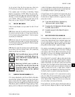
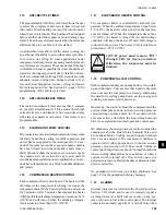
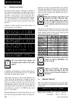
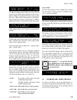
Pump Down:
This message indicates that both refrigerant systems
are in a pumpdown cycle. Pumpdown display messages
occur on shutdowns where the cooling load has been
met, or when a system switch is turned OFF. Note that
only one compressor could be pumping down, as shown
in the following display:
See Section 1.18 (page 109) for details of pumpdown
control.
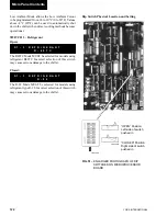
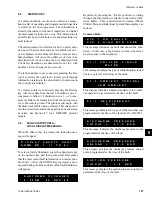
Incorrect Refrigerant Warning:
The Incorrect Refrigerant Warning will occur if the DIP
Switch setting for refrigerant type and the type pro-
grammed into the micro “at the factory” are not the
same. This message will be displayed until the non-
programmable "factory" programmed refrigerant type
and DIP Switch setting agree.
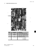
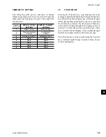
Power Failure Warning:
The Power Failure Warning will only be displayed on
“power restoration” after a “power loss”, if manual re-
start on power failure is selected under the PROGRAM
key (Page 139). If manual restart on power failure has
been selected, the following warning message is dis-
played indefinitely on power restoration and the chiller
will not run until the UNIT Switch is cycled OFF-and-
on to restart the unit. This safety is available for users
who desire a chiller lock-out on power failure.
This is typically not a desirable feature.
When this message appears, the chiller will not run and
the Unit Switch must be cycled OFF and ON to start
the unit.
2.4
ANTICIPATION CONTROL STATUS
MESSAGES
Anticipation controls are built into the software to pre-
vent safety shutdowns by automatically overriding the
temperature controls, if system conditions approach
safety thresholds. This avoids total loss of cooling re-
sulting from a lockout by a safety control.
Anticipation controls monitor discharge pressure, mo-
tor current and suction temperature for each compres-
sor and if maximum limits are approached, the slide
valve loading of the respective compressor will be re-
duced to avoid exceeding the limit.
Displays of anticipation safety control messages and
their meanings are as follows:
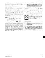
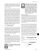
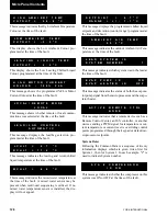
Discharge Pressure Limiting:
Discharge Pressure Limiting takes effect when com-
pressor discharge pressure nears the point at which the
high pressure cutout would shut the system down. When
the above message appears, discharge pressure has ex-
ceeded the programmable threshold and the compres-
sor is being unloaded in an effort to prevent shutdown
on the high pressure cutout. The operation of this safety
is important if condenser coils become dirty, if there is
a problem with the condenser fan operation, or if ex-
treme ambient or load conditions occur (see Section
8.2 / High Discharge Pressure Unload Point [page 139]
for more details).
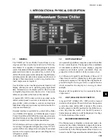
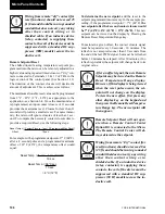
Compressor Motor Current Limiting:
The Motor Current Limiting message indicates that a
compressor motor current has reached a programmable,
Bas, or remote limit and the system is being unloaded
to assure that motor current does not become exces-
sively high causing a fault (see also Section 8.2 / High
Motor Current Unload Point, page 141; Section 3.5,
Motor Current Key, page 121; Section 1.10, page 105).
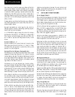
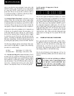
Suction Temperature Limiting:
The Suction Temperature Limiting message applies only
when the chiller is set for Water Cooling Mode (see
S Y S
#
S U C T
L I M I T I N G
S Y S
#
S U C T
L I M I T I N G
R E P R O G R A M
T Y P E
O F
R E F R I G E R A N T
T O
R U N
! !
P O W E R
F A I L U R E
! !
C Y C L E
U N I T
S W I T C H
S Y S
#
C U R R
L I M I T I N G
S Y S
#
C U R R
L I M I T I N G
S Y S
#
D S C H
L I M I T I N G
S Y S
#
D S C H
L I M I T I N G
S Y S
1
P U M P I N G
D O W N
S Y S
2
P U M P I N G
D O W N
S Y S
1
P U M P I N G
D O W N
S Y S
2
C O M P
R U N N I N G
9
Summary of Contents for eco2 YCAS0425EB
Page 26: ...26 YORK INTERNATIONAL This page intentionally left blank Product Description ...
Page 49: ...49 YORK INTERNATIONAL FORM 201 18 NM8 This page intentionally left blank 7 ...
Page 60: ...60 YORK INTERNATIONAL FIG 20 CONTINUED ELEMENTARY DIAGRAM Technical Data ...
Page 65: ...65 YORK INTERNATIONAL FORM 201 18 NM8 WIRING DIAGRAM WYE DELTA START LD03229 FIG 23 CONT D 7 ...
Page 66: ...66 YORK INTERNATIONAL FIG 23 CONTINUED ELEMENTARY DIAGRAM Technical Data ...
Page 68: ...68 YORK INTERNATIONAL FIG 24 POWER PANEL FRONT INSIDE VIEW WYE DELTA START Technical Data ...
Page 71: ...71 YORK INTERNATIONAL FORM 201 18 NM8 LD03282 LD03283 LD03284 FIG 27 DETAIL A 7 ...
Page 74: ...74 YORK INTERNATIONAL FIG 32 DETAIL B Technical Data LD03285 ...
Page 75: ...75 YORK INTERNATIONAL FORM 201 18 NM8 FIG 33 DETAIL C 7 3 4 5 6 7 8 5 6 3 4 7 8 9 10 LD06841 ...

