background image

Summary of Contents for GY9

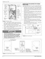
Page 1: ...not try to light any appliance Do not touch any electrical switch do not use any phone including cell phone in your building Leave the building immediately Immediately call your gas supplier from a ne...

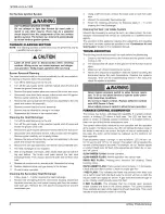
Page 2: ...ally examine the exte rior sections of the vent combustion air piping and the vent con nectors to be sure that they are physically sound without holes or excessive corrosion 2 Examine the vent pipe ma...

Page 3: ...place any part of the control system and any gas control which has been under water Operating Instructions 1 STOP Read the safety information above 2 Set the thermostat to the lowest setting 3 Turn of...

Page 4: ...r filters located on the top of the fur nace in an external filter rack To check filters you should 1 Follow the instructions to turn off the appliance before servicing 2 Filters are installed in the...

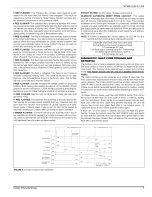
Page 5: ...at is connected to the HI COOL ter minal on the control board The fan off setting is fixed at 60 seconds for SEER enhancement Heating Cycle When the thermostat switch is set on HEAT and the fan is set...

Page 6: ...leaning the Heat Exchanger Cleaning the Vent Air Intake System Should it be necessary to service the vent air intake system the man ufacturer recommends this service be conducted by a qualified servic...

Page 7: ...h no G sig nal check to see that the wire from the G terminal on the board to the wall thermostat has not broken or disconnected STEADY ON RED Control failure Replace control board 60 MINUTE AUTOMATIC...

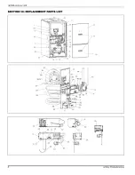
Page 8: ...167808 UUM A 1205 SECTION II1 REPLACEMENT PARTS LIST 43 11 34 44 _ 32 17 27 J 26 56 57_ 22 49 42 5 19j 30 65 4t 33 79 9 37 45 23 14 o 6 10 28 36 8 Unitary Products Group...

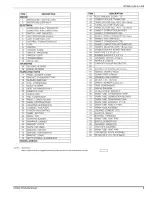
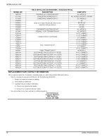
Page 9: ...2 83 ft Req d 44 TUBING SILICONE Preformed 45 TUBING SILICONE Gray 188 ID 1 25ft Req d 46 GASKET COMBUSTION BLOWER 47 GASKET CONDENSATE PAN 48 GASKET UPPER CONDENSATE PAN 2Req d 49 GASKET GAS CONTROL...

Page 10: ...TOM RETURN FILTER KIT 1 FILTER BOTTOM RETURN FILTER KIT 1 4 FILTER USED WITH ALL MODELS ALL MODELS EXCEPT 120 MBH ALL MODELS 40 60 100 120 80 1200 80 1600 ALL MODELS ALL MODELS 14 1 2 CABINET 17 1 2 C...

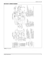
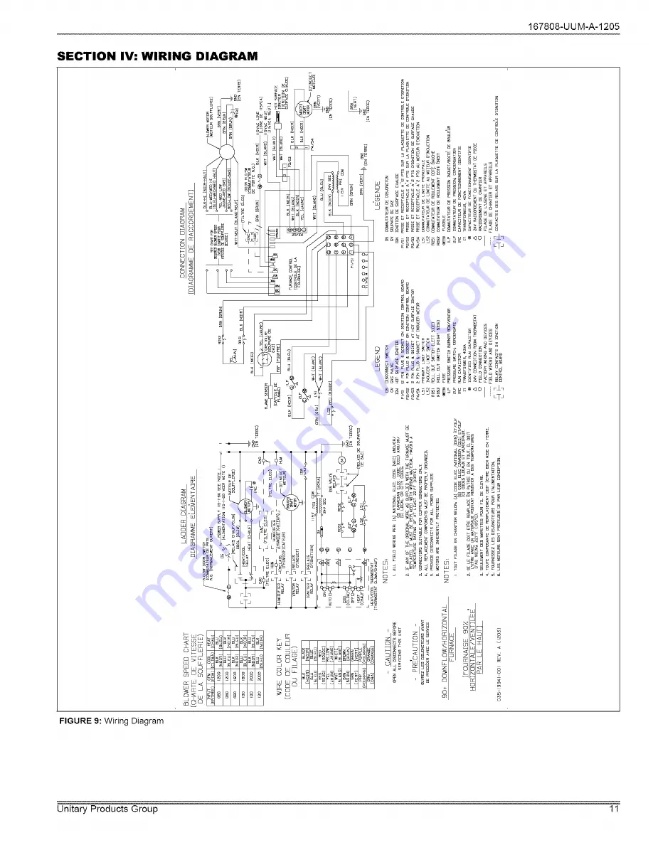
Page 11: ...167808 UUM A 1205 SECTION IV WIRING DIAGRAM i B z_ w _ 8_ c_ W 8 w 8 FIGURE 9 Wiring Diagram Unitary Products Group 1 1...

Page 12: ...s installed in the United States and Canada EXCLUSIONS This warranty does not cover any 1 Shipping labor or material charges 2 Damages resulting from transportation installation or servicing 3 Damages...

Reviews: