Unitary Products Group
3
339033-YTG-A-0607
NOTES:
1. Airflow expressed in standard cubic feet per minute (CFM).
2. Motor voltage at 115 V.
3. NR = Operation at this static pressure is not recommended.
FILTER PERFORMANCE
The airflow capacity data published in the “Blower Perfor-
mance” table listed above represents blower performance
WITHOUT filters. To determine the approximate blower per-
formance of the system, apply the filter drop value for the fil-
ter being used or select an appropriate value from the “Filter
Performance” table shown.
NOTE:
The filter pressure drop values in the “Filter Perfor-
mance” table shown are typical values for the type of filter
listed and should only be used as a guideline. Actual pres-
sure drop ratings for each filter type vary between filter manu-
facturer.
NOTES:
1. Air velocity through throwaway type filters may not exceed 300
feet per minute. All velocities over this require the use of high
velocity filters.
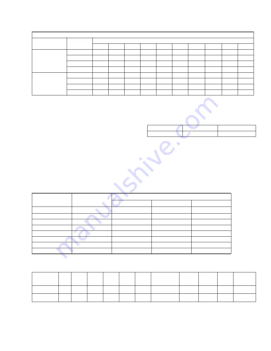
BLOWER PERFORMANCE CFM
AIRFLOW WITH TOP RETURN - WITHOUT FILTERS (CFM)
Models
Speed
Tap
External Static Pressure, Inches W.C.
0.1
0.2
0.3
0.4
0.5
0.6
0.7
0.8
0.9
1.0
GY9F064C16DH11
High
2071
2026
1981
1935
1864
1796
1713
1625
1532
1401
Medium High
1583
1590
1569
1554
1532
1502
1457
1409
1327
1221
Medium Low
1256
1275
1275
1288
1275
1265
1232
1187
1126
1023
Low
937
939
936
945
942
936
912
874
810
726
GY9F080C16DH11
High
1996
1961
1938
1896
1836
1779
1707
1625
1531
1399
Medium High
1449
1480
1495
1488
1488
1449
1417
1368
1299
1208
Medium Low
1167
1192
1192
1187
1202
1192
1182
1140
1097
1018
Low
932
900
871
840
805
761
710
663
641
623
RECOMMENDED FILTER SIZES
CFM
Cabinet Size
Top Return Filter in
1600
C
(2) 14 x 20
FILTER PERFORMANCE - PRESSURE DROP INCHES W.C. AND (KPA)
Airflow Range
Minimum
Opening Size
Filter Type
Disposable
Washable Fiber
Pleated
CFM
in
2
In W.C.
In W.C.
In W.C.
0 - 750
230
0.01
0.01
0.15
751 - 1000
330
0.05
0.05
0.20
1001 - 1250
330
0.10
0.10
0.20
1251 - 1500
330
0.10
0.10
0.25
1501 - 1750
380
0.15
0.14
0.30
1751 - 2000
380
0.19
0.18
0.30
2001 & Above
463
0.19
0.18
0.30
UNIT CLEARANCES TO COMBUSTIBLES
Application
Top
Front
Rear
Left
Side
Right
Side
Flue
Floor/
Bottom
Closet
Alcove
Attic
Line
Contact
Downflow
1
3
0
0
0
0
1"
*
Yes
Yes
Yes
No
Horizontal
0
3
0
1
1
0
Combustible
No
Yes
Yes
Yes
†
*
Special floor base or air conditioning coil required for use on combustible floor.
†
Line contact only permitted between lines formed by the intersection of the rear panel and side panel (top in horizontal position) of
the furnace jacket and building joists, studs or framing.


