FORM 160.49-M1
17
YORK INTERNATIONAL
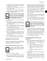
3. Thoroughly lubricate shaft with clean YORK re-
frigerant oil prior to installation. For HD and HF
compressors, proceed to Step 6.
4. Install the sleeve spacer on the shaft and slide it all
the way onto the shaft.
5. Thoroughly lubricate C-ring with clean YORK re-
frigerant oil. Install the C-ring with the open side of
the ring facing the compressor.
Care needs to be taken when install-
ing the C-ring to prevent damage to
the ring on any burrs on the shaft or
on the snap ring grove that may be on
the shaft of older compressors.
6. Install the shaft seal cover o-ring in the rotor sup-
port housing.
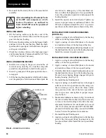
7. Using guide studs install the seal cartridge in the
rotor support housing and secure it with the existing
3/8" mounting screws.
8. Before tightening the shaft seal sleeve set screw,
rotate the compress shaft to insure that the set
screws straddle the shaft keyway.
9. Without removing the two shaft seal sleeve retain-
ing clips, tighten the four accessible set screws to
the compressor shaft.
10. Remove the retaining clips and tighten the remain-
ing setscrews. Torque all six setscrews to 60 inch
pounds. Install retaining clips in the Operating Posi-
tion on seal face.
11. Re-connect the oil drain line and re-install the com-
pressor coupling if no further service is planned.
DISASSEMBLY OF ROTOR SUPPORT
The following paragraphs outline the procedure for sepa-
rating the rotor support from the rotor scroll if it be-
comes necessary to service internal parts:
Removing the Rotor Supports from Rotor Scroll
For steps 1 thru 4 follow procedures
listed on previous pages of this in-
struction.
1. Remove the compressor coupling.
2. Remove all external piping from the rotor support.
3. Using proper rigging techniques, temporarily sup-
port the weight of the back end of the rotor support.
4. Taking care that the motor is properly supported,
remove the bolts that hold the motor to the motor
adaptor. Remove the motor from the chiller and sit
away from work area. See “
Motor Removal and
Replacement
” described on page
13
.
DO NOT
remove the motor adaptor from the compressor.
5. Insert eyebolt into the top of the rotor support and
using proper rigging methods support the weight of
the rotor support.
6. Remove (2) of the 12 point cap screws holding the
rotor support to the rotor scroll. Insert guide pins in
place of the (2) cap screws.
7. Loosen the remaining cap screws. Do not remove
the (2) set screws/studs with nuts from the bottom
of the flange near the drain pipe. Remove the nuts
only.
On the HF family of compressors it
may be necessary to temporarily rig a
support for the oil sump. The sumps
on these compressors are not attached
to the shell.
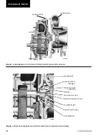
8. Use (3) of the cap screws as jacking screws in the
tapped holes provided to loosen the rotor support
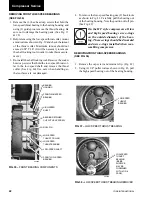
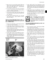
from the rotor scroll. (See Fig. 25) Carefully pull
the rotor support out of the rotor scroll. Rotate the
shaft by hand when removing the rotor support to
prevent damage to the impeller inlet seal ring.
9. The rotor support can now be removed and rested
on the end of the motor adapter.
REMOVING THE IMPELLER (size 46 & larger)
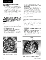
(See Fig. 26)
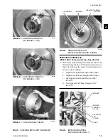
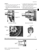
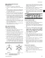
1. Before removing the impeller, measure and record
the following. (See Fig. 27) Position compressor so
that it is sitting on the correct horizontal plane to
assure correct readings.
a. Impeller rim Runout (Design 0.003" max.)
b. Impeller eye Runout (Design 0.002" max.)
c. High Speed Axial thrust (Design 0.008"
to 0.021”)
d. Low Speed Axial Thrust (Design 0.011"
to 0.019")
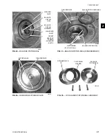
2. Install the gear locking tool on the low-speed shaft.
(See Fig. 52)
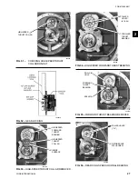
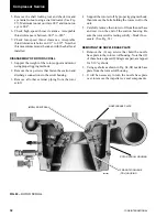
3. Remove the 3 (or 6) screws that hold the impeller
to the high-speed shaft. (See Fig. 28) Pull the im-
peller from the high-speed shaft. Use care when
removing the impeller so that the balance piston seal
is not damaged.
2


