YORK INTERNATIONAL
30
INSTALLING GEARS
1. Oil the bearing surfaces on the drive end of the
low-speed gear, and carefully insert the low-speed
gear into the rear bearing.
2. Oil the rear bearing surface on the high-speed shaft,
and insert it into the rear bearing. Mesh the high-
speed and low-speed gear teeth and rotate the gears
as the gear is installed.
3. Check the clearance between the high-speed gear
and the spray header. Clearance should be 0.12"min.
/ 0.18" max. Adjust if necessary.
INSTALLING BEARING HOUSING
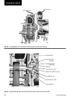
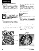
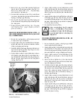
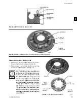
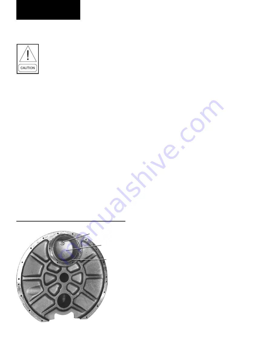
1. Install a new o-ring in the groove around the oil
reservoir cavity. (See Fig. 61). Coat the o-ring with
a suitable o-ring lubricant to hold it in the groove.
2. Insert (2) guide pins 180 degrees apart into the ro-
tor support.
3. Lift the bearing housing and carefully push in place
over the guide pins. Note location of dowel pins. Be
careful not to damage any of the machined sur-
faces on either the high-speed or low-speed shafts.
Leave the guide pins in position to help support the
bearing housing.
4. Install the cap screws and dowel pins. Tighten cap
screws to proper torque as outlined in Table 4. On
HF style compressors install the (2) ½" cap screws
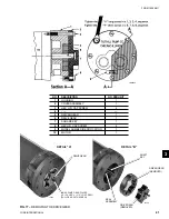
used to secure the dowel pins as shown in Fig. 42A.
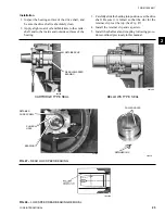
INSTALLING FRONT HIGH-SPEED BEARINGS
(SEE FIG. 36)
1. Apply a coating of oil and Molykote to the bearing
surfaces of the high-speed shaft.
2. Apply a coating of oil and Molykote to the inside
and outside surfaces of the high-speed bearing.
3. Carefully slide the high-speed bearing into place over
the shaft and into the cavity in the bearing housing.
Install the retainer clip and cap screw.
INSTALLING FRONT LOW-SPEED BEARINGS
1. Apply a coating of oil and Molykote to the bearing
surface of the low-speed shaft.
2. Apply a coating of oil and Molykote to the inside
and outside surfaces of the low-speed bearing.
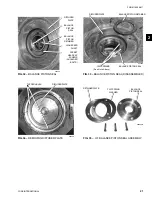
3. Carefully slide the low-speed bearing into place over
the shaft and into the cavity in the bearing housing.
Be sure hole in bearing flange engages roll-pin in
bearing housing. (See Fig. 42)
4. Re-install the shaft locking tool.
5. Apply a coating of oil and Molykote to the lapped
surfaces of the low-speed thrust collar, using care
that no damage occurs. Place the thrust collar
into position on the end of the low-speed shaft,
insert cap screws, and tighten to proper torque.
(See Table 4)
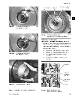
6. Mount a dial indicator as shown in Fig. 39 and check
the run-out of the thrust collar. (It will be necessary
to remove the shaft locking tool to take this mea-
surement) Maximum run-out should not exceed
.001" T.I.R. If run-out exceeds .001"T.I.R. DO NOT
proceed with further assembly; contact the YORK
Factory Service Department for assistance.
7. Re-install the shaft locking tool.
8. Apply a coating of oil and Molykote to the bearing
pads of the low-speed thrust bearing and to the
low-speed thrust collar. Install the low-speed thrust
bearing.
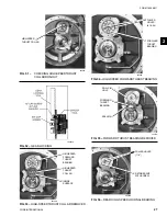
FIG. 61 –
BEARING HOUSING
CHECK VALVE
OIL
RESERVOIR
“O” RING
26328A
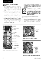
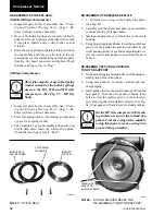
8. Re-install the Proximity Probe or Pressure Switch
assembly.
After reinstalling the Proximity Probe
on the HD style compressor, a Cali-
bration Procedure, as outlined in
Form 160.49-M2, must be performed
before restarting.
Compressor Service


