YORK INTERNATIONAL
38
Oil Pump Service
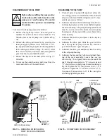
5. Using a hammer and block of hard wood, tap the
outside end of the stud to loosen the internal lever.
DO NOT REMOVE THE SPECIAL STUD.
6. Remove the cover plate cap screws.
7. Slide the external level from control shaft and cover
plate from the control shaft.
8. Remove the external lever and the control shaft
cover from the control shaft.
9. Replace the existing gasket with a new one.
10. Install the two new “O” rings and one “O” ring in
their respective grooves in the new control shaft -
small ring in groove in taper. Liberally coat the con-
trol shaft (“O” rings and neoprene sleeve) and the
inside of the cover plate with YORK Valve Stem
Lubricant. DO NOT lubricate the tapered surfaces
of the shaft.
11. Slide the new shaft with “O” rings into position
over the special stud.
12. Install the cover plate, but do not tighten the cap
screws at this time.
13. Tighten the nut on the outside end of the stud against
the end of the control shaft to pull the internal lever
hard up on the taper of the shaft.
14. With the cover plate loosely installed, close the vanes
by turning the nut on the outside end of the stud.
Position the external lever on the control shaft so
that the indicator pin on the lever aligns with the
closed “C” mark on the housing. Push external le-
ver arm slightly to seat on taper.
15. Remove the nut and stud.
16. Install the 6" cap screw and washer. Draw the cap
screw tight. Move the external lever to the “open”
and “closed” positions, to check the indicator points
on the cover plate. Readjust the external lever po-
sition, if necessary.
17. Using a torque wrench, tighten the bolt to a torque
of 75 ft. lbs.
18. Move the external lever to its midposition (vanes
half open) and tighten the cover plate cap screw to
a torque of 35 ft. lbs.
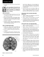
THIS IS IMPORTANT
AND ASSURES THAT THE SLEEVE WILL
TWIST EQUALLY WHEN THE VANES ARE
MOVED TO EITHER THE WIDE OPEN OR
THE FULLY CLOSED POSITION.
19. Connect the linkage to the external lever.
When connecting the vane linkage to the electric motor,
rotate the motor shaft to the closed position and con-
nect the vane linkage while holding the vanes in the
closed position. Operate the vane motor open and closed
several times to be sure the motor does not jam at ei-
ther end of its travel. Adjust as necessary by either length-
ening or shortening the distance between the motor link-
age and the external lever to be sure the vanes are wide
open and tightly closed as the motor rotates from one
end of its travel to the other.
IT IS IMPORTANT
that the arm length from motor
centerline to force point, the arm length from control
shaft centerline to force point and the length of connec-
tion arm be the same as they were set at the factory.
Also, the angular position of the motor shaft must be as
it came from the factory.
SECTION 3
OIL PUMP SERVICE
OIL PUMP
The oil pump furnishes oil to the compressor’s rotating
components prior to start-up, during compressor opera-
tion and during coastdown. If it is necessary to service
the oil pump, use the following procedure:
REMOVING OIL PUMP FROM THE OIL SUMP
1. De-energize the power supply to the oil pump and
oil sump heater. Remove electrical leads from fusite
connections and transducers.
2. Drain oil from oil sump through drain valve in right
side of shell.
3. Remove oil eductor line and oil line at the pressure
regulator. (Note that on Rev Level E chillers and
above that the oil regulating valve has been replaced
by using a variable speed oil pump).
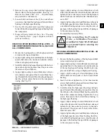
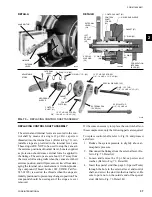
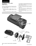
4. Remove the (16) 5/8" hex nuts from the oil sump
cover. (See Fig. 76)
5. After all nuts are removed, pull the oil sump cover
loose and remove the cover and oil pump assembly.
(See Fig. 76)

