background image

FORM 160.54-M1(503)

155

YORK INTERNATIONAL

DISPLAY TEST

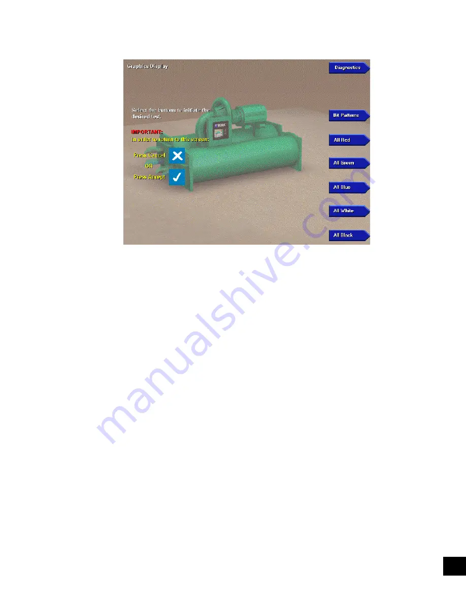
FIG. 67 –

 DISPLAY TEST MAIN SCREEN

00337VIP

Each of the Display Diagnostics is accessed from this 
screen. After each diagnostic is performed, return to this 
screen, from which the next diagnostic can be se lect ed. 
Refer to description of Display operation in Sec tions 5 
through 7 of this book.

PROCEDURE

 1.   Press the appropriate keypad key to perform the 

de sired test from the list below.

 2.   Press the 

CANCEL 

(X) or 

ENTER 

(

) key to ter-

 mi nate test and return to 

DISPLAY TEST MAIN


screen, from which another test can be se lect ed.

 3.   When all the desired tests have been performed, 

press the 

DIAGNOSTICS 

key to return to the 

MAIN DIAGNOSTICS

 screen.

  •   

Bit Patterns -

 This test is used to detect jitter and 

align ment defects. It veri

fi

 es proper operation and 

com pat i bil i ty  of  the  Microboard  Display  Con trol ler 
with the display. Four vertical bars of green, dark 
blue, light blue and yellow, outlined by a red bor der 
are dis played. If the vertical bars are not sta ble or 
straight, or the red border is not com plete ly vis i ble, 
then either the Microboard Program Jump ers are not 
con

fi

 gured cor rect ly for the installed dis play or the 

Microboard Dis play controller is de fec tive. Re fer 
to Figure 66.

  •   

All Red -

 This test veri

fi

 es the operation of all of 

the red pixels. All of the red pixels are turned on 
to cre ate a completely red screen. Any red pixels 

that do not turn on will appear as black dots on the 
dis play. If any black dots appear, 

fi

 rst ascertain it is 

not caused by dirt that is lodged between the dis play 
surface and the protective plastic cover. It is normal 
for a small num ber of randomly spaced pix els to not 
illuminate. It is not necessary to replace the display 
if a small num ber of black dots appear. They will not 
be visible on the normal screens dis played outside 
of this di ag nos tic mode. However, large black areas 
would be in dic a tive of a de fec tive display.

  •   

All Green -

 This test veri

fi

 es the operation of all of 

the green pixels. All of the green pixels are turned 
on to cre ate a completely green screen. Refer to 
de scrip tion of “All Red” test above.

  •   

All Blue -

 This test veri

fi

 es the operation of all of 

the blue pixels. All of the blue pixels are turned on to 
create a completely blue screen. Refer to de scrip tion 
of “All Red” test above.

  •   

All White -

 This test veri

fi

 es the display’s abil i ty 

to turn on all pixels to display a completely white 
screen. Any pixel that does not turn on will appear 
as a black dot. Refer to description of “All Red” test 
above.

  •   

All Black -

 This test veri

fi

 es the display’s abil i ty 

to turn off all pixels to display a completely black 
screen. Any pixel that does not turn off will appear as 
a red, green, blue or white dot. Refer to de scrip tion 
“All Red” test above.

24

Summary of Contents for MAXE OPTIVIEW YK

Page 1: ...essors until 8 02 371 02780 102 MOD B Solid State Starter CE P Compressors until 8 02 371 02779 102 MOD B Solid State Starter NEMA 4 12 P Compressors until 8 02 MODEL YK THROUGH STYLE F 371 02778 103...

Page 2: ...terials This individual shall also be familiar with and comply with all applicable governmental standards and regulations pertaining to the task in question SAFETY SYMBOLS The following symbols are us...

Page 3: ...G4 CM F MOTOR CODE 60 Hz 50 Hz CH CX 5CE 5CT CJ CY 5CF 5CU CK CZ 5CG 5CV CL CA 5CH 5CW CM CB 5CI 5CX CN DA 5CJ 5DA CP DB 5CK 5DB CR DC 5CL 5DC CS DD 5CM 5DD CT DE 5CN 5DE CU DF 5CO 5DF CV DH 5CP 5DG C...

Page 4: ...ECTION 21 SMART FREEZE PROTECTION 129 SECTION 22 SURGE PROTECTION 131 SECTION 23 SYSTEM CALIBRATION 133 Electro Mechanical Starter Applications 133 Solid State Starter Applications 134 Mod B Serial Da...

Page 5: ...155 Serial Inputs Outputs Test 157 Digital Iinputs Outputs Test 159 Anallog Inputs Test 162 SECTION 25 SYSTEM COMMISSIONING CHECKLIST 165 SECTION 26 SERVICE INFORMATION LETTERS BULLETINS 168 SI0006 So...

Page 6: ...D367 DISPLAY 49 FIG 20 LIQUID CRYSTAL DISPLAY ASSEMBLY SHARP LQ10D421 DISPLAY 49 FIG 21 LIQUID CRYSTAL DISPLAY ASSEMBLY NEC NL6448AC33 24 DISPLAY 50 FIG 22 LIQUID CRYSTAL DISPLAY ASSEMBLY LG SEMICON L...

Page 7: ...IABLE SPEED DRIVE VSD 97 FIG 54 OIL PUMP VSD OIL HEATER CONTROL INTERFACE 98 FIG 55 OIL PUMP VSD SPEED CONTROL SIGNAL 98 FIG 56 MICROGATEWAY INTERFACE BLOCK DIAGRAM 99 FIG 57 PRESSURE TRANSDUCERS 101...

Page 8: ...operating conditions ASystemCommissioningChecklistisprovidedasreference of items to be performed during chiller commissioning Chillers that are equipped with P Compressors have certain component vari...

Page 9: ...ed to restart the chiller Diagnostic Routines allow service analysis of the fol lowing functions Display Analog inputs Digital inputs Digital outputs Serial Data ports Before beginning any troubleshoo...

Page 10: ...is a DC voltage that is analogous to the temperature it is sensing Typical output voltage range of both is 0 5 to 4 5VDC These are analog inputs to the OptiView Control Center Digital Inputs are on of...

Page 11: ...sure Safety Cutout Switch HPCO than supplied on other compressor applications This switch is mounted on the condenser shell but has a different wiring in terface to the I O Board and Motor Controller...

Page 12: ...overload and power fault protection for the compressor motor Current Trans formers located in the compressor motor terminal box along with rectifying and calibration circuitry provide an analog voltag...

Page 13: ...ONTACT CLOSURE HIGH SPEED THRUST BEARING LIMIT SWITCH P COMPRESSORS AND STYLE F AND LATER CHILLERS WITH G AND H5 8 COMPRESSORS VARIABLE ORIFICE CONTROL PRE ROTATION VANE CONTROL STATUS ALARM CHILLER S...

Page 14: ...LER SHUTDOWN REMOTE LEAVING CHILLED WATER TEMP CURRENT LIMIT SETPOINTS CONTACT CLOSURE VARIABLE ORIFICE CONTROL PRE ROTATION VANE CONTROL STATUS ALARM CHILLER SOLENOID VALVES OIL PUMP STARTER OIL HEAT...

Page 15: ...5 SERIAL DATA SCR CONTROL FACTORY MOUNTED CHILLED AND CONDENSER LIQUID THERMAL TYPE FLOW SENSORS STYLE F AND LATER CHILLERS CHILLER TEMPERATURES PRESSURES CONDENSER REFRIGERANT LEVEL HIGH SPEED THRUST...

Page 16: ...X SERIAL DATA TX RX SERIAL DATA VSD LOGIC BOARD VSD FILTER BOARD FACTORY MOUNTED CHILLED AND CONDENSER LIQUID THERMAL TYPE FLOW SENSORS STYLE F AND LATER CHILLERS CHILLER TEMPERATURES PRESSURES CONDEN...

Page 17: ...SOLENOIDS VANES CLOSING TIME DEPENDENT ON INITIAL VANE POSITION OIL PRESSURE CHECK OIL PUMP ON 150 SEC 2 5 MIN SYSTEM RUN SYSTEM PRELUBE VANES CLOSING BEFORE SHUTDOWN SYSTEM COASTDOWN SYSTEM SHUTDOWN...

Page 18: ...5 MIN SYSTEM COASTDOWN SYSTEM SHUTDOWN TIME IN SECONDS MINUTES DISPLAY MESSAGE 600 10 RESTART ONLY AFTER FIFTH SUCCESSIVE RESTART RESTART IF FIVE SUCCESSIVE RESTARTS HAVE NOT OCCURED SYSTEM RUN SYSTEM...

Page 19: ...a replaceable component Refer to YORK Renewal Parts List Form 160 54 RP1 The version of the Memory card is an alpha numeric code that represents the application and revision level The version is prin...

Page 20: ...longer operate it applies a reset signal to the Micro The Micro responds by de energizing the run digital output through the FPGA shutting down the chiller and retrieving the Power Failure message fr...

Page 21: ...code identifying the Manufacturer is compared to other loca tions that contain the manufacturer s name If these values are the same it is pass If they are different it is fail 4 Mini card checksum The...

Page 22: ...eypad is read every Program cycle The Micro selects the MUX inputs Microboard J7 J8 J9 for input to the A D Converter by writing sequential addresses to the FPGA The FPGA holds each address until a ne...

Page 23: ...put to a 5VDC regulator The output of this regu lator powers only the Analog circuits This includes the MUX A D converter CM 2 module Mod A Solid State Starter Logic Board Transducers and Thermistors...

Page 24: ...6 to determine the type of Display DRAM installed as explained above It also reads wire jumpers PID0 through PID3 via Microboard J5 on the Display Interface Board to determine the manufacturer of the...

Page 25: ...ss The PC 104 Port J16 J17 is an industry standard ar rangement of two connectors that allows the stacking of 3 6 x 3 8 inch printed circuit boards PC 104 Modules on the Microboard The circuits on the...

Page 26: ...nsed the solid state relay output is turned on causing it to conduct current through the 7 5K ohm microboard load resistor to the 5vdc This applies 4Vdc to the microboard input evaporator J7 14 conden...

Page 27: ...any unused Flash Memory Cards toYORK per the Warranty Return Procedure If Flash Memory Card 031 01797 001 is used it must be a version C MLM 01 04 or later ie 05 06 etc to be used with BIOS Eprom U45...

Page 28: ...YORK INTERNATIONAL 28 FORM 160 54 M1 503 Microboard FIG 7 MICROBOARD LD07776...

Page 29: ...ECTOR FIG 8 FLASH MEMORY CARD LD06855 LD04049 WRITE PROTECT SWITCH OPTIONAL MUST BE IN ENABLED POSITION CINS CINS GND VCC 3V 5V KEY ALIGNMENT NOTCH PAD 60 PAD 30 PAD 31 PAD 1 LD04047 LD04050 WRITE ENA...

Page 30: ...LIGHT CONTROL DATA BUS XCVR SERIAL DATA PORT 1 DISPLAY INTERFACE BOARD BACKLIGHT INVERTER BOARD DIGITAL INPUTS DIGITAL OUTPUTS SERIAL DATA PORTS 2 THROUGH 5 ANALOG INPUTS 5VDC REF LVG CHILLED WATER TE...

Page 31: ...of the Backlight enable signal Pins 1 2 12VDC 0VDC SHARP LQ10D421 display Pins 2 3 5VDC 0VDC SHARP LQ10D367 NEC NL6448AC33 24 and LG Semicon LP104V2 W displays JP5 Display backlight power Determines...

Page 32: ...ons JP31 PC 104 Port DMAassignment Assigns selected PC 104 DMArequest to PIRQ1 on the micropro cessor DMArequest selections are silk screened on the Microboard adjacent to the program jumper Not used...

Page 33: ...od is 180 seconds in duration Oil Pump runs for 167 seconds OFF Standard prerun System Prelube period is 50 seconds in duration Oil Pump runs for 37 seconds 4 Diagnostics Enables or disables software...

Page 34: ...ether the watchdog protection is enabled or disabled NEVER disable the watchdog pro tection Severe compressor or chiller damage could result The ability to disable the watchdog protection is provided...

Page 35: ...OM 4A NOTE 1 COM 2 COM 3 COM 5 OPTO COUPLE RS 485 RS 232 RS 485 RS 232 MICRO GATEWAY PRINTER MULTI UNIT COMMS NOT USED OPTIONAL I O VARIABLE SPEED DRIVE ADAPTIVE CAPACITY CONTROL BOARD 4 3 5 2 7 6 8 9...

Page 36: ...lers equipped with factory mounted thermal type flow sensors FACTORY MOUNTED EVAPORATOR THERMAL TYPE FLOW SENSOR style F and later chillers note 2 REMOTE CURRENT LIMIT SETPOINT REMOTE LEAVING CHILLED...

Page 37: ...he Microboard is commanding a relay to de energize logic low 1VDC when com manding a relay to energize Relay K18 is different from all other relays on the I O Board it has a 115VAC coil It provides th...

Page 38: ...tacts Open or System Cycling Contacts Open cycling shutdown They remainclosedforthedurationoftheshutdownoruntil the Keypad COMPRESSOR switch is placed in the Stop Reset O position whereupon they open...

Page 39: ...on chiller shutdown coincident with the be ginning of System Coastdown K13 Compressor Motor Starter start TB1 6 16 Contacts close coincident with the beginning of Sys tem Run They remain closed for 0...

Page 40: ...S 115VAC 115VAC 115VAC TB4 7 TB4 1 TB4 8 TB4 1 TB4 19 TB4 20 TB4 1 TB4 12 REMOTE START REMOTE STOP CHILLED WATER FLOW SWITCH REMOTE CURRENT LIMIT SETPOINT PWM REMOTE LEAVING CHILLED LIQUID TEMP SETPOI...

Page 41: ...TYPICAL OPTO COUPLER CIRCUIT FIG 16 I O BOARD TYPICAL FIELD CONNECTIONS OPTO COUPLER TYPICAL 20 CKTS 5VDC J19 21 JI Y JI 22 23 NEUTRAL TB3 2 TB4 X TB3 X LD04057 115VAC TB3 1 TB4 1 TB4 X OPTO COUPLER J...

Page 42: ...USED NOT USED NOT USED NOT USED OIL HEATER ON OFF P compressors and all style F and later chillers equipped with Flash Memory Card version C MLM 01 07 xxx or later version OIL PUMP STARTER Style C and...

Page 43: ...TRAL Q2 Q1 K13 K18 K14 TB1 6 TB1 16 16 1 53 CM TM NOTE 2 TO I O BOARD J2 1 TO I O BOARD TB3 32 START RUN STOP 1 HP Not applicable to P compressors or style F and later chillers See Note 3 See inset be...

Page 44: ...IVER J1 29 J1 28 REFRIGERANT LEVEL CONTROL OPEN REFRIGERANT LEVEL CONTROL CLOSE 3 2 TB1 158 TB1 160 TB1 159 1 2 2 1 G G TRIAC DRIVER TRIAC DRIVER J1 31 J1 30 NOT USED NOT USED REFRIGERANT LEVEL CONTRO...

Page 45: ...at will pass through the window The conduction of each transistor is controlled by a signal from the Display Controller on the Microboard The overall pixel color is a result of the gradient of red gre...

Page 46: ...a different Display Interface Board required for each Display ap plication and each has a unique jumper configuration that identifies the Display A complete explanation of this process is included in...

Page 47: ...t glass surface to prevent it from being scratched Peel off very slowly to prevent static damage Always remove control power from the OptiView control center before con necting or disconnecting wires...

Page 48: ...ar of Display 3 Disconnect LampAC power connector from Back light Inverter Board FIG 18 DISPLAY MOUNTING LD04062 4 Using small Phillips screwdriver remove lamp retaining screw 5 Grasp Lamp AC power co...

Page 49: ...FACE BOARD NOT AVAILABLE BACKLIT INVERTER BOARD NOT AVAILABLE INVERTER CABLE NOT AVAILABLE MOUNTING PLATE LABEL CH1 CN2 CN1 CN3 NOTE 1 Configure Microboard Program Jumpers per label NOTE 1 Configure M...

Page 50: ...SPLAY NOTE 1 Configure Microboard Program Jumpers per label LIQUID CRYSTAL DISPLAY NEC NL6448AC33 24 LABEL MOUNTING PLATE INVERTER CABLE NOT AVAILABLE BACKLIT INVERTER BOARD NOT AVAILABLE DISPLAY INTE...

Page 51: ...KLIGHT BULB 025 34564 000 4564 1 4 FIG 22 LIQUID CRYSTAL DISPLAY ASSEMBLY LG SEMICON LP104V2 W LD05525 NOTE 1 Configure Microboard Program Jumpers per label 640 CLKS 640 COLUMNS 31US VSYNC 480 ROWS 16...

Page 52: ...TION B DIRECTION C FIG 24 DISPLAY SHARP LQ10D367 LAMP REPLACEMENT LD04067 FIG 25 DISPLAY SHARP LQ10D421 LAMP REPLACEMENT LD04068 BLACK LOCKING TAB BLACK LOCKING TAB FLAT HEAD SCREWDRIVER A A REAR VIEW...

Page 53: ...G 26 DISPLAY NEC NL6448AC33 24 LAMP REPLACEMENT LD04069 NOT AVAILABLE AT THIS TIME FIG 27 DISPLAY LG SEMICON LP104V2 W LAMP REPLACEMENT LD05527 LAMP HOLDER BEZEL RETAINING SCREW WIRE white GND side WI...

Page 54: ...oard Program Jumper JP2 if OUT 0VDC If P31 is IN the voltage at J1 31 is GND if OUT 0VDC The Display reads these voltages and adopts a scan mode as follows SHARP LQ10D367 LQ10D421 Displays SHARP displ...

Page 55: ...ERNATIONAL FIG 28 DISPLAY INTERFACE BOARD LD04070 LG SEMICON LP104V2 W NEC NL6448AC33 24 DISPLAYS 031 01765 001 PID0 IN PID1 3 OUT P30 P31 OUT SHARP LQ10D367 LQ10D421 DISPLAYS 031 01765 002 PID0 OUT P...

Page 56: ...equired voltage The Microboard provides the Backlight Enable signal This signal turns the lamp on and off Some manufacturers re quire this signal to be 12VDC others require 5VDC Program Jumper JP4 mus...

Page 57: ...over the range of 0 to 2 5VDC 0VDC produces maximum 100 lamp brightness 2 5VDC produces minimum 0 brightness Voltages between these values produce a linear brightness between 0 and 100 This display h...

Page 58: ...4 2 0 2 5VDC 0VDC MAX 100 Brightness 2 5VDC MIN 0 Brightness Refer to Fig 10 and Microboard Program Jumpers JP7 JP8 3 Refer to Microboard Program Jumper JP5 4 N C No Connection NOTES 1 ON 5VDC OFF 0VD...

Page 59: ...reads the columns Alogic low in any column indicates a key in that column and row is pressed For example if at the time row 4 is being driven low if column 3 is low then the Micro concludes the key a...

Page 60: ...YORK INTERNATIONAL 60 FORM 160 54 M1 503 Keypad FIG 32 KEYPAD CONNECTOR LD04074...

Page 61: ...FORM 160 54 M1 503 61 YORK INTERNATIONAL FIG 33 KEYPAD LD04075 LD04076 8...

Page 62: ...e Thermistors Proximity Probe and Mo tor controller Board CM 2 Mod A Solid State Starter LogicBoardorVSDACCBoard ThispermitsallAnalog circuitstobepoweredbythesamesupply eliminatingany offsets caused b...

Page 63: ...Mod A Solid State Starter Logic Trigger Board Mod B Solid State Starter Adap tive Ca pac i ty Con trol VSD 5 Refer to Fig 45 46 47 for Proximity Probe Power Connections Not applicable to P compressors...

Page 64: ...compressor motor current is at 100 FLA Fig 38 contains a formula to calculate the resistance of RES required to achieve 1 0VDC at 100 FLA The 100 FLA value is located on a label adhered to the inside...

Page 65: ...It then addresses channel 7 ignoring channels 1 through 6 to read the analog motor current voltage The Microboard interprets this analog value in terms of FLA and displays it upon operator keypad req...

Page 66: ...INTERNATIONAL 66 FORM 160 54 M1 503 Current Module CM 2 FIG 36 CM 2 CURRENT MODULE ELECTRO MECHANICAL STARTER APPLICATION LD04079 FIG 37 CM 2 CURRENT MODULE ELECTRO MECHANICAL STARTER APPLICATIONS LD0...

Page 67: ...through CT twice before connecting to power supply C Requires passing motor lead through CT three times before con necting to power supply D Calculates resistance of RES to achieve 1 0VDC at FLA MOTO...

Page 68: ...tdown on all LCSSS initiated shutdowns After power has been applied to the system the Microboard will attempt to establish communications with the Logic Trigger Board If unsuccessful within 10 attempt...

Page 69: ...a cycling shutdown and LCSSS RUN SIGNAL is displayed on the System Details line of the display The Logic Trigger Board transmits the following pa rameters over the serial communications link for displ...

Page 70: ...effect The Microboard calculates the Full Load Amps FLA by dividing the high est phase of the 3 phase motor current received from the Logic Trigger Board by the value programmed for the FULL LOAD AMPS...

Page 71: ...K Service Manual 160 46 OM3 1 As shown in Fig 41 the Logic Board of this model starter is mounted inside the OptiView Control Center FIG 40 SOLID STATE STARTER LOGIC BOARD INTERLOCK JUMPER BETWEEN NO...

Page 72: ...s than 3 seconds POWER FAULT is displayed The respective Ph Rot Loss or Trig OOL LED illuminates and remains illuminated until manu ally reset with the S1 RESET switch The chiller will automatically r...

Page 73: ...o 3 45VDC 100 FLA 0 0 to 1 20VDC 104 FLA 0 1 0 2 Phase C AC Power Line voltage as follows 300VAC scale VDC out VAC 67 9 600VAC scale VDC out VAC 135 8 0 1 1 3 Phase B AC Power Line voltage Same as Pha...

Page 74: ...SUPPLY MICRO BOARD I O BOARD L C S S S LOGIC PCB 031 00936 2 36 37 2 36 37 J1 J19 J1 2 MOTOR CONTROLLER SHUTDOWN J1 36 STOP J1 37 START 25 16 1 TB5 TB1 J2 TB6 16 53 1 TB6 25 24 3 1 2 J2 STOP CONTACTS...

Page 75: ...between the Microboard and the VSD components The communications is in master slave form The VSD Logic Board and Harmonic Filter Logic Boards act as slaves to theACC and theACC acts as a slave to the...

Page 76: ...nter s I O Board input J2 1 This notifies the Microboard that a VSD shutdown has occurred The Microboard requests the cause of the shutdown by sending a Fault Data Request command While this request i...

Page 77: ...tion 25 In AUTO speed control mode the ACC Board controls the speed It determines the optimum compressor mo tor speed frequency over the range of 30 to 60 50 Hz and sends this value to the VSD Logic B...

Page 78: ...Flash Memory Card version C MLM 01 06 xxx and later or P compressors with C MLM 04 02 xxx and later and the 50 or 30 sensitivity is selected PRV movement is further reduced during low load conditions...

Page 79: ...lowed If a surge is detected within this 5 minute period it is not plotted on the Surge Map but the speed is increased by the amount as described above This is repeated as long as the compressor conti...

Page 80: ...serial communications link for Delta P P calculation these pressures are also applied directly from the Microboard to the MUX mul tiplexer for Delta P surge detection Also applied to the MUX is the ou...

Page 81: ...DAPTIVE CAPACITY CONTROL ACC BOARD TPE HARMONIC FILTER FRAME PULSES TPD HARMONIC FILTER DATA MICROBOARD RECEIVE LED VSD TRANSMIT LED VSD RECEIVE LED MANUAL SURGE POINT SWITCH MICRO TPC POWER FAIL MICR...

Page 82: ...ERFACE LD04085 MICRO BOARD POWER SUPPLY ACC BOARD VSD LOGIC BOARD HARMONIC FILTER LOGIC BOARD VARIABLE SPEED DRIVE SERIAL DATA TX SERIAL DATA RX SERIAL DATA CLK FRAME SERIAL DATA EVAP PRESSURE COND PR...

Page 83: ...AL DATA CR5 CR4 VS XMT VS RCV VSD LOGIC BOARD J10 J3 3 1 RED GREEN SERIAL DATA CR6 CR7 YM RCV YM XMT 2 3 HARMONIC FILTER LOGIC BOARD J6 2 1 POWER SUPPLY TPB TPA TO ALL CKTS MICRO BOARD MICRO BOARD MUX...

Page 84: ...n the calibration procedure must be repeated to establish a new Reference Position Since this Reference Position value is stored in the BRAM U52 memory device on the Microboard field replacement of ei...

Page 85: ...nt a new Flash Memory Card 031 01797 001 must be ordered at the same time as the Probe If an appropriate Flash Memory Card is not used the chiller will be prevented from starting due to safety shutdow...

Page 86: ...1 2 1 2 NOTES 1 24VDC Reference for Proximity Probe Low Supply Voltage Cycling Shutdown 2 CM 2 Board Solid State Starter Logic Board or Adaptive Capacity Control Board as determined by the Starter Ap...

Page 87: ...M 2 Board Solid State Starter Logic Board or Adaptive Capacity Control Board as determined by the Starter Application FIG 47 PROXIMITY PROBE INTERFACE PROBE PART NUMBER 025 35900 000 24VDC POWER SUPPL...

Page 88: ...M1 503 FIG 48 PROXIMITY PROBE LD05530 LD06510 LD05529a 24VDC PROBE 2 0 YORK PART NUMBER 025 35900 000 2 75 UNIVERSAL 12 24VDC PROBE YORK PART NUMBER 025 xxxxx 000 FUTURE 24VDC PROBE 2 0 YORK PART NUM...

Page 89: ...ch exposing the pressure switch to the pressure inside the compressor A set of normally closed contacts inside the switch open when the switch is exposed to a pressure of 15 to 25 PSIG One side of the...

Page 90: ...RK INTERNATIONAL 90 FORM 160 54 M1 503 GRD PIN GRN YEL PINS 1 2 BLK GRN YEL PRESSURE SWITCH BREAK AWAY PROBE FIG 50 HIGH SPEED THRUST BEARING LIMIT SWITCH High Speed Thrust Bearing Limit Switch LD0686...

Page 91: ...ensor The level will be displayed as 0 when input 23 on the ANALOG I O Diagnostic Screen is 0 37VDC and 100 when it is 4 31VDC The Level Sensor is calibrated to output values that would produce these...

Page 92: ...gnal as required from the Microboard to the actuator to maintain the level to the Level Setpoint The duration of the signal deter mines the magnitude of change to the Orifice position The duration of...

Page 93: ...etpoint Therefore longer Periods would produce longer output pulses for the same error resulting in unstable operation under certain conditions TheorificevalvemovementisanimatedontheRefrigerant LevelC...

Page 94: ...29 TB1 163 161 162 REFER TO FIG 16 CLOSE OPEN LEVEL OUTPUT GND 12VDC 3 2 1 LIQUID LEVEL SENSOR ORIFICE VALVE ACTUATOR BARBER COLEMAN ACTUATOR 115VAC FIELD L1 L2 2 3 X 5 115VAC IT 1 2 24 VAC ORIFICE V...

Page 95: ...D For the remainder of System Run and the Coast down period it operates it over the same frequency range to maintain the pressure to the programmed Oil Pressure Setpoint When the chiller is started 13...

Page 96: ...frequency is increased or decreased 0 5 Hz to increase or decrease the oil pressure However if the error is 6 PSID the value programmed for Control Period Setpoint determines the relative magnitude o...

Page 97: ...illers When the oil pump is not operating the heater is turned on and off to maintain a target value of 50 F above the Condenser Saturation Temperature If the calculated tar get value is 160 F the tar...

Page 98: ...z 60 0 Hz 33 5 Hz 42 5 Hz 51 0 Hz 0 17 SEC 0 35 SEC 0 52 SEC FIG 54 OIL PUMP VSD OIL HEATER CONTROL INTERFACE FIG 55 OIL PUMP VSD SPEED CONTROL SIGNAL LD04093 LD04094 1 2 3 SPEED COMMAND START STOP 12...

Page 99: ...remote device that is connected to the MicroGate way is going to provide remote Start Stop signals re mote Leaving Chilled LiquidTemperature and or remote Current Limit Setpoint resets the Control Sou...

Page 100: ...er outputs during a 3 second period beginning 10 seconds after the start of the System Prelube period are compared to determine the offset between them During this period since both of the transducers...

Page 101: ...5 28678 004 V VOLTS DC P PRESSURE PSIG V P 4 375 58 75 P 58 75 x V 4 375 25 0 142 5 201 25 260 0 500 2 500 3 500 4 500 EVAPORATOR TRANSDUCER R134a WATER BRINE APPLICATIONS YORK PART NO 025 28678 112 1...

Page 102: ...side of the thermistor is connected to Ground through a series resistor on the Microboard thus forming a voltage divider network The temperature applied to the thermistor determines the resistance va...

Page 103: ...57 1 8243 22 06 5 52 1 8274 22 15 5 47 1 8304 22 24 5 42 1 8335 22 33 5 37 1 8365 22 42 5 32 1 8396 22 51 5 27 1 8426 22 60 5 22 1 8457 22 69 5 17 1 8487 22 78 5 12 1 8518 22 87 5 07 1 8548 22 96 5 0...

Page 104: ...2 1567 31 67 0 18 2 1597 31 76 0 13 2 1628 31 84 0 09 2 1658 31 93 0 04 2 1689 32 02 0 01 2 1719 32 10 0 06 2 1750 32 19 0 11 2 1780 32 28 0 16 2 1811 32 37 0 21 2 1841 32 45 0 25 2 1872 32 54 0 30 2...

Page 105: ...5 18 2 4952 41 42 5 23 2 4982 41 51 5 28 2 5012 41 60 5 33 2 5043 41 69 5 38 2 5073 41 78 5 43 2 5104 41 87 5 48 2 5134 41 96 5 53 2 5165 42 05 5 58 2 5195 42 14 5 63 2 5226 42 23 5 68 2 5256 42 31 5...

Page 106: ...62 08 16 71 3 1660 62 18 16 77 3 1690 62 28 16 82 3 1721 62 39 16 88 3 1751 62 49 16 94 3 1782 62 59 17 00 3 1812 62 69 17 05 3 1843 62 80 17 11 3 1873 62 90 17 17 3 1904 63 01 17 23 3 1934 63 11 17 2...

Page 107: ...1 76 08 24 49 3 5501 76 20 24 56 3 5532 76 32 24 62 3 5562 76 44 24 69 3 5593 76 57 24 76 3 5623 76 69 24 83 3 5654 76 81 24 90 3 5684 76 93 24 96 3 5715 77 05 25 03 3 5745 77 18 25 10 3 5776 77 30 25...

Page 108: ...531 25 86 3 41 1 9580 26 00 3 33 1 9629 26 14 3 26 1 9678 26 28 3 18 1 9727 26 42 3 10 1 9775 26 56 3 02 1 9824 26 71 2 94 1 9873 26 85 2 86 1 9922 26 99 2 78 1 9971 27 13 2 71 2 0020 27 27 2 63 2 006...

Page 109: ...69 2 7686 49 59 9 77 2 7734 49 74 9 86 2 7783 49 89 9 94 2 7832 50 04 10 02 2 7881 50 19 10 11 2 7930 50 34 10 19 2 7979 50 48 10 27 2 8027 50 63 10 35 2 8076 50 78 10 43 2 8125 50 93 10 52 2 8174 51...

Page 110: ...7 3 4326 71 72 22 07 3 4375 71 91 22 17 3 4424 72 09 22 27 3 4473 72 28 22 38 3 4521 72 46 22 48 3 4570 72 64 22 58 3 4619 72 83 22 69 3 4668 Temp F Temp C Vin 73 01 22 79 3 4717 73 20 22 89 3 4766 73...

Page 111: ...51 68 10 93 2 1268 51 83 11 02 2 2217 51 97 11 10 2 2266 52 12 11 18 2 2314 52 27 11 26 2 2363 52 42 11 35 2 2412 52 57 11 43 2 2461 52 72 11 51 2 2510 52 87 11 60 2 2559 53 02 11 68 2 2607 53 17 11...

Page 112: ...77 02 25 01 3 0127 77 19 25 11 3 0176 77 36 25 20 3 0225 77 53 25 30 3 0273 77 70 25 39 3 0322 77 86 25 48 3 0371 78 03 25 57 3 0420 78 20 25 67 3 0469 78 37 25 76 3 0518 78 54 25 86 3 0566 78 71 25...

Page 113: ...3 6572 102 33 39 08 3 6621 102 55 39 20 3 6670 102 78 39 33 3 6719 103 00 39 45 3 6768 103 22 39 57 3 6816 103 45 39 70 3 6865 103 67 39 82 3 6914 103 89 39 94 3 6963 104 12 40 07 3 7012 104 35 40 20...

Page 114: ...5 18 75 0 6348 66 08 18 93 0 6396 66 40 19 11 0 6445 66 72 19 29 0 6494 67 04 19 47 0 6543 67 36 19 65 0 6592 67 68 19 82 0 6641 68 00 20 00 0 6689 68 31 20 17 0 6738 68 62 20 35 0 6787 68 93 20 52 0...

Page 115: ...4404 106 39 41 33 1 4453 106 59 41 44 1 4502 106 79 41 55 1 4551 106 99 41 66 1 4600 107 19 41 78 1 4648 107 39 41 89 1 4697 107 59 42 00 1 4746 107 79 42 11 1 4795 107 99 42 22 1 4844 108 18 42 33 1...

Page 116: ...29 2 2412 137 10 58 39 2 2461 137 28 58 49 2 2510 137 46 58 59 2 2559 137 65 58 70 2 2607 137 83 58 80 2 2656 138 01 58 90 2 2705 138 19 59 00 2 2754 138 37 59 10 2 2803 138 56 59 20 2 2852 138 74 59...

Page 117: ...0566 169 07 76 16 3 0615 169 28 76 27 3 0664 169 49 76 39 3 0713 169 70 76 51 3 0762 169 91 76 62 3 0811 170 12 76 74 3 0859 170 33 76 86 3 0908 170 54 76 97 3 0957 170 75 77 09 3 1006 170 96 77 21 3...

Page 118: ...7 94 44 3 7305 202 25 94 59 3 7354 202 54 94 75 3 7402 202 82 94 91 3 7451 203 11 95 07 3 7500 Temp F Temp C Vin 203 40 95 23 3 7549 203 69 95 39 3 7598 203 99 95 56 3 7646 204 28 95 72 3 7695 204 57...

Page 119: ...5 34 86 3 488 98 06 36 70 3 566 101 50 38 61 3 644 105 10 40 61 3 722 108 90 42 73 3 801 112 92 44 96 3 879 117 17 47 32 3 957 121 76 49 87 4 035 Temp F Temp C Vin 0 04 17 76 1 135 2 79 16 23 1 214 5...

Page 120: ...ocal BASE value The Microboard COM 4B RS 232 Serial Port J2 receives the Setpoints in serial data form from the MicroGateway located inside the OptiView Control Center enclosure The MicroGateway recei...

Page 121: ...late the setpoint for various inputs as follows Setpoint 100 mA x 3 5 For example if the input is 8mA the setpoint would be set to 72 as follows Setpoint 100 8 x 3 5 100 28 72 4 20mA As shown in Fig 1...

Page 122: ...riately to accept the desired signal type as follows The appropriate Remote Mode must be selected ANALOG Remote Mode must be selected when using a voltage or current signal input DIGITAL Remote Mode m...

Page 123: ...t 40 5 45 F 2 10VDC As shown in Fig 12 connect input to Microboard J22 3 signal and J2 5 Gnd A 2VDC signal produces a 0 F offset A 10VDC signal produces the maximum allowed offset 10 F or 20 F above t...

Page 124: ...115VAC to the I O Board TB4 19 for 1 to 11 seconds As shown in Fig 14 connect dry closure relay contacts between I O Board TB4 19 input and TB4 1 115VAC A contact closure time pulse width of 1 second...

Page 125: ...ints and Reset Procedures section of this book The PRVposition is displayed as XX on the COM PRESSOR Screen and Warning Vanes Uncalibrated is displayed on the System Details line of the display until...

Page 126: ...ave elapsed the valve is driven fully closed If the chiller is equipped with a Variable Speed Drive VSD whenever the VSD is running at full speed 50 60 Hz the Hot gas Bypass valve is driven to the ful...

Page 127: ...en these extremes are linearly scaled The Pre rotation Vanes PRV potentiometer 2 5K Ohms is connected to P1 providing a 0 to 5VDC volt age from a 12VDC source that represents PRV positon Potentiometer...

Page 128: ...SER TRANSDUCER PRV POTENTIOMETER POSITIONING SIGNAL MICRO BOARD EVAPORATOR TRANSDUCER EVAP PRESSURE COND PRESSURE 18 21 12 11 12 11 2 3 J8 RS 485 COM 3 J12 ACTUATOR POSITIONING VANE POSITION J9 P1 P10...

Page 129: ...omes a minimum of 34 0 F Unless Smart Freeze protection is activated the fixed Low Evaporator Pressure Safety thresholds R22 54 3 PSIG 29 6 F R134a 25 0 PSIG 28 7 F are used SMART FREEZE protection is...

Page 130: ...iquid Temperature Setpoint as programmed or a minimum of 36 0 F 2 The Low Evaporator Pressure Safety shutdown threshold is the same as Smart Freeze Disabled above If the Leaving Chilled Liquid Tempera...

Page 131: ...VDC calculated as surge sensi tivity setpoint x 300 x 1 22 1000 Each time a surge event is detected the SURGE DE TECTED LED indicator on the SURGE PROTECTION Screenilluminatesfor5secondsandtheTOTALSUR...

Page 132: ...cleared otherwise another 10 minute period is initiated Al ternating with this message is Warning Excess Surge Detected that is displayed until manually reset with the Warning Reset key in OPERATOR a...

Page 133: ...ccepted and the dialog box disappears The chiller will begin to operate based on the new value If out of range the value is not accepted and a message describing why it is not acceptable is displayed...

Page 134: ...keys as required to achieve a motor current equivalent to 100 FLAas indicated by the clamp onAmmeter Loose locking nut on Potentiometer R34 on CM 2 and adjust until the motor current value on the Disp...

Page 135: ...motor AC power line Logic Board Program Jumper Place Jumper J5 300V 600V in appropriate position per the Compressor Motor AC Power Line application as follows 600V Place over pins 1 2 for 380 400 415...

Page 136: ...to achieve the proper starting cur rent of 0 45 x Delta Locked rotor Amps on the highest phase Turning R38 Clockwise increases current Counterclockwise decreases current Multiple starts could be requ...

Page 137: ...e the value Pre rotation Vanes Position Potentiometer When initially installed the Potentiometer should be set so that the feedback voltage as measured between the wiper white wire and common black wi...

Page 138: ...ect MOTOR Screen 3 Press KWH RESET key 4 Use numeric keypad keys to enter desired value 5 Press ENTER key VSD Frequency Control The VSD Frequency can be manually controlled as follows 1 At the Keypad...

Page 139: ...CALIB key The measured gap is entered as the Reference Position Log this value on the Label adhered to the inside of the OptiView Control Center door This remains the Reference Position until the Comp...

Page 140: ...ows the chiller to be started REFRIGERANT LEVEL CONTROL A complete description of the Condenser refrigerant level control and the Setpoints that affect this control are provided in the Refrigerant Lev...

Page 141: ...tween the REFRIGERANT LEVEL CONTROL Screen and the ANALOG I O Diagnostics screen The REFRIGERANT LEVEL CONTROL Screen is used to manually control the Orifice and the refrigerant level is displayed the...

Page 142: ...o select the Setpoint to be programmed 4 If the Dialog box begins with the word Enter use the numeric keypad keys to enter the desired value If it begins with Select use the and keys to select desired...

Page 143: ...ss level using access code 1 3 8 0 2 Select EVAPORATOR Screen 3 On the EVAPORATOR Screen press the BRINE LOW EVAPORATOR CUTOUT key 4 Using numeric keypad keys enter desired value 5 Press ENTER key LEA...

Page 144: ...R Screen 4 Press SMART FREEZE key 5 Use and keys to select ON or OFF 6 Press ENTER key EVAPORATOR REFRIGERANT TEMPERATURE If the chiller is equipped with an Evaporator Refrigerant Temperature sensor t...

Page 145: ...ERATIONS screen 3 Press NUMBER of STARTS or OPERATING HOURS key as appropriate 4 Using numeric keypad keys enter desired num ber 5 Press ENTER key key Setpoints The following are the Setpoints and ran...

Page 146: ...changed The numeric keypad keys can also be used to enter numbers Continue this process until all desired values have been entered 7 After all desired values have been entered in pre vious step press...

Page 147: ...he first changeable area in the selected category will be outlined in a green selection box The procedure can be terminated anytime after this by pressing the CANCEL X key 5 Use the S and T keys to mo...

Page 148: ...OG DETAILS Screen display levels of this information On the SECURITY LOG Screen accessible from the HISTORY Screen the Setpoint Setpoint Category and new Setpoint value are listed and numbered in reve...

Page 149: ...he Thermal type Analog or Paddle type Digital flow sensors in the style F chillers With these versions the actual Flow Sensor type present must be entered using the Flow Switch Setpoint Oil Heater Out...

Page 150: ...PSID Style F P Compr Limit Switch TB1 64 10 0 sec Analog thermal type 25 PSID Not applicable to Style C and earlier chillers FLASH MEMORY CARD VERSION C MLM 01 08 XXX Chiller Style Compressor Proxmity...

Page 151: ...and condenser Flash Memory Card version C MLM 01 08 xxx and later allow these chillers to use either the thermal type or field installed paddle type flow sensor The thermal type sensors interface to...

Page 152: ...F chillers all compressors 160 73 PW1 Electro mechanical Starter 160 73 PW2 Mod B Solid State Starter 160 73 PW3 Variable speed Drive There are two versions of the Diagnostics screens avail able as fo...

Page 153: ...elected Some of the diagnostics have sub screens that are accessed from the selected diagnostic screen The sub screens are shown indented below Main screen Keypad test Display test Bit patterns test A...

Page 154: ...ypad a Disconnect the ribbon cable from the Keypad b Identify row column coordinate of the key to be tested Refer to Figure 33 c In the Keypad connector locate the pins of the row column coordinate of...

Page 155: ...ion of all of the red pixels All of the red pixels are turned on to create a completely red screen Any red pixels that do not turn on will appear as black dots on the display If any black dots appear...

Page 156: ...inuity test on all conductors of the Interface Board An open circuit would indicate the Interface Board is defective 3 Microboard a With the All Red test selected the voltage at Microboard J5 6 throug...

Page 157: ...rm ing each test the Service Technician must install a wire loop back connection as described below Refer to Sec tion 3 and Figure 11 of this book for description of the Serial data Ports PROCEDURE 1...

Page 158: ...ated COM 2 Three tests are performed Test data is sent from TX J13 5 to RX J13 3 at 19200 Baud DTR J13 7 is set to a Logic High and read at DSR J13 2 DCD J13 1 RTS J13 4 is set to a Logic High and rea...

Page 159: ...screen ac cording to a Terminal number on the I O Board and b Microboard Program Jumpers and Program DIP Switches Figure 14 shows the devices con nected to these terminals Tables 1 and 2 list the fun...

Page 160: ...a defective component is found during any of the following steps replace the component as instructed and repeat the digital Inputs Procedure above to determine if the problem has been resolved 1 Remov...

Page 161: ...output should be at a Logic High 10 0VDC level With the output at a Logic High level the relay contacts should be open If they are not open replace the I O Board If it is 10 0VDC remove the ribbon cab...

Page 162: ...ers Section 17 Thermistors Section 18 Proximity Probe Section 13 Refrigerant Level Control Section 14 Solid State Starter Mod A only Section 11 and Current Module CM 2 Section 10 0 2 5VDC Analog suppl...

Page 163: ...ired channel by pressing the SELECT CHANNEL key and using the and keys to place the arrow head next to the desired channel Then freeze the address of that channel to the Solid State Starter or CM 2 MU...

Page 164: ...e Microboard 4 Using a Voltmeter verify the correct address is being sent from the Microboard to the Solid State Starter Logic Board or CM 2 Board Freeze ad dress as described above If the address is...

Page 165: ...ue and all calibrations have been performed The programming of some of the Setpoints require a SER VICE access level To assure access to all Setpoints login at SERVICE access level before beginning Th...

Page 166: ...fy Switch S1 Ydelta 57 or all others setting ____ Verify Pot R16 LRA FLA ratio setting ____ Verify slide bar resistor RES setting ____ Verify 105 FLA calibration ____ Verify 100 FLA display Variable S...

Page 167: ...nter the following ____ Automatic print logging Enable disable ____ Automatic printer logging start time ____ Automatic print logging interval ____ Printer type ____ Report type STATUS SETPOINTS SCHED...

Page 168: ...cted conditions TRIG GERS and a selected TRIGGER DELAY If START is selected data collection will not begin until all triggers have been satisfied and any selected TRIGGER DELAY has elapsed Data collec...

Page 169: ...Speed Drive 1 The compressor motor VSD phase A B and C output current to the motor is now displayed on the VSD Tun ing Screen 2 The new 351HP VSD is supported In this model the three Inverter Assembl...

Page 170: ...e closing during the Soft Shutdown if a standard Local Stop is initiated with the front panel Rocker Switch or if any faults other than the following occur the Soft Shutdown is terminated and it will...

Page 171: ...er data Trend print mode Trend view mode Leaving Chilled Liquid Temperature Control Sensitivity Setpoint In addition to the NORMAL and 50 selections provided in previous software versions a 30 selecti...

Page 172: ...rformed If either the 50 or 30 Leaving Chilled Liquid Temperature SENSITIVITY Setpoint is selected Pre rotation Vane movement is further reduced when the chiller is operating at low load When the Vane...

Page 173: ...FORM 160 54 M1 503 173 YORK INTERNATIONAL 26 This page intentionally left blank...

Page 174: ...3 002 The various YK chiller modification level style compressor combinations are equipped differently and have dif ferent control requirements Variables include the following High Speed Thrust bearin...

Page 175: ...re The lower temperature differential between the two thermistors indicates the liquid is flowing A higher differential indicates no flow Each device operates from a 24Vac power source and has a solid...

Page 176: ...the Refrigerant Level Raise output is energized for the length of the pro grammable VALVE PRESET TIME setpoint 0 to 100 seconds default 50 Service access level After pre positioning the valve is held...

Page 177: ...FORM 160 54 M1 503 177 YORK INTERNATIONAL 26 This page intentionally left blank...

Page 178: ...y compressor the FLOW SWITCH key appears on the OPERATIONS Screen allowing the flow sensor type to be entered The selections are Analog thermal type or Digital paddle type If Analog is selected the pr...

Page 179: ...perature Same as phase A above VSD High Phase C Inverter Baseplate Temperature Same as phase A above Harmonic Filter High Baseplate Temperature The chiller has shutdown because the Baseplate temperatu...

Page 180: ...ler G H5 8 compr The previous choice of Style F chiller J compr is now Style F chiller J H3 compr The Chiller Style Compressor selections are shown below Chiller Style Compressor Proxmity Sense Oil He...

Reviews: