YORK INTERNATIONAL
20
FORM 160.54-M1(503)
Flash Memory Cards are revised to add new features,
enhancements and program corrections. Each time they
are revised, the revision level of the affected portion of
the program (controls or language) increments. Each
time they are revised, a Service Information Bulletin is
issued that describes the new features. Those bulletins
that have been issued to
date, are located at the rear of this
manual.
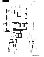
The
Micro
controls the chiller by read ing and ex e cut ing
the Program in struc tions in a sequence determined by
the Program. Under Program control, the Micro reads
the Analog and Digital Inputs to de ter mine the op er -
at ing con di tions and con trols Digital Outputs based
upon these inputs. These inputs are com pared to stored
thresh olds to determine if a Safety or Cycling shutdown
is re quired. If a threshold has been exceeded, a shut down
is per formed and the ap pro pri ate message is retrieved
from the Program and displayed on the Liquid Crystal
Dis play. As operating conditions require, status mes-
sag es are retrieved and dis played. The Keypad is read as
Dig i tal Inputs. When an operator presses a key to request
a display, the Micro in ter prets the request, re trieves the
display from the Program and displays it. The Program
assembles data in the correct format for transmission
through the Serial Data Ports to pe riph er al devices. The
Program also instructs the Micro to re spond to requests
from pe riph er al devices for serial data transmissions.
The
MUX
(multiplexer) is a switching device that only
al lows one analog input through at a time. The inputs
are selected sequentially by the Micro per Program
in struc tions.
The
A/D Converter
converts each analog input to a
12-bit word. In this form, the values can be stored in
mem o ry de vic es, compared to values in the Pro gram,
trans mit ted through Serial Ports or sent to the Display
Con trol ler for display. Control signals to start con ver sion
pro cess are from the Micro via the FPGA.
The
Watchdog
circuit monitors the +5VDC supply
from the ex ter nal Power Supply to determine when
a power fail ure is occurring. Just prior to the supply
de creas ing to a level where the Micro and supporting
cir cuits can no longer operate, it applies a reset signal
to the Micro. The Micro responds by de-energizing the
run digital output through the FPGA, shutting down the
chiller and retrieving the
Power Failure
mes sage from
the Pro gram and send ing it to the Display Con trol ler
for dis play. Sim i lar ly, when power is
fi
rst ap plied af ter
a pow er failure, it main tains the Micro in a reset state
until the +5VDC has returned to a suf
fi
cient level. The
Watch dog circuit also assures that all the Program in-
struc tions are being performed and that the Program has
not latched-up, bypassing im por tant safe ty thresh olds. If
the Pro gram has latched-up, The Micro initiates a Safety
shut down and displays
WATCH DOG – SOFT WARE
REBOOT
message.
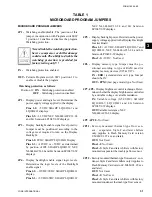
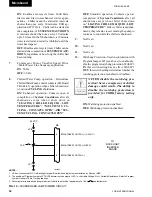
The
Program Jumpers
(Table 1) and
Program Switch-
es
(Ta ble 2) are used to alter the Pro gram op er a tion
or configure the Microboard hard ware for spe cif ic
op er a tion. This allows the Program and Microboard
to be universal for all applications of the chiller. Refer
to Table 1 and 2 for the function of each jumper and
switch. The po si tion of some can be de ter mined and set
by the Service Technician to meet the desired operation
or chiller ap pli ca tion. The position of others is dictated
by the size, type or style of certain OptiView Control
Center com po nents and thus the position is de ter mined
by the YORK Factory. The required position of each
is listed in these tables. The Program Jumpers are wire
bridges that are either left in place or cut. The Pro gram
Switches are min ia ture switches that are placed in ei ther
the
ON
or
OFF
position.
The
DRAM
(dynamic random access memory) is a non
battery-backed memory device. The Micro stores data
here temporarily for further processing. Data in this de-
vice is lost during power failures. DRAM differs from
RAM in that DRAM must be periodically re freshed in
circuit.
The
BIOS EPROM
(basic input/output system eras able
programmable read only memory) is a memory device
that contains the bootstrap or power-up pro gram. It is
located in socket location U45. This EPROM is re place -
able. Refer to YORK Renewal Parts List Form 160.54-
RP1. The EPROM version is an alpha-numeric code
that represents the application and revision level. The
version is printed on a label adhered to the EPROM’s
surface. The version code is as follows:
Microboard
C. MLM. 00. XX.
Revision level. In cre ments 01, 02 etc.
YM Chiller BIOS EPROM
MAXE™
Chiller
Commercial
Chiller
Summary of Contents for MAXE OPTIVIEW YK
Page 28: ...YORK INTERNATIONAL 28 FORM 160 54 M1 503 Microboard FIG 7 MICROBOARD LD07776...
Page 60: ...YORK INTERNATIONAL 60 FORM 160 54 M1 503 Keypad FIG 32 KEYPAD CONNECTOR LD04074...
Page 61: ...FORM 160 54 M1 503 61 YORK INTERNATIONAL FIG 33 KEYPAD LD04075 LD04076 8...
Page 173: ...FORM 160 54 M1 503 173 YORK INTERNATIONAL 26 This page intentionally left blank...
Page 177: ...FORM 160 54 M1 503 177 YORK INTERNATIONAL 26 This page intentionally left blank...


