64
YORK INTERNATIONAL
Under Voltage Safety
The Under Voltage Safety assures that the system is
not operated at voltages where malfunction of the micro-
processor could result in system damage. Whenever the
microprocessor senses an onboard power supply fail-
ure, the chiller is shut down. Restart will occur when
power is restored. The microprocessor circuitry is ca-
pable of operating at voltages 10% below the nominal
115VAC supply to the panel.
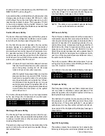
An example of the Under Voltage Safety display mes-
sage is shown below:
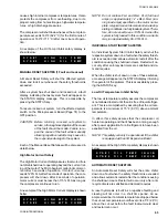
Flow Switch
The microprocessor monitors the closure of the flow
switch to assure that water flow is present in the evapo-
rator which prevents freeze-ups. The flow switch “dry”
contacts are connected between terminals 13 & 14 of
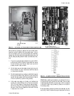
the TB3 Terminal Block (Fig. 12). If the flow switch opens,
the chiller will shut down and the following status mes-
sage will be displayed.
Closure of the flow switch, when flow is present, will
cause the message to disappear and auto-restart will
occur.
CAUTION: NEVER BYPASS A FLOW SWITCH. THIS
WILL CAUSE DAMAGE TO THE CHILLER
AND VOID ANY WARRANTIES.
Power Failure Safety
Whenever power is removed or lost and then reapplied,
auto-restart will occur after a 2 minute anti-recycle timer
elapses. This is the same anti-recycle timer which is
programmable from 5-10 minutes; however, it automati-
cally is set to 2 minutes after a power failure.
This safety assures that the motor has a minimum of 2
minutes to cool under any circumstances allowing much
of the internal heating due to starting to be dissipated
before another start occurs.
ANTICIPATION SAFETY CONTROLS
Anticipation controls are built into the software to pre-
vent safety shutdowns by automatically overriding tem-
perature controls if system pressures near safety thresh-
olds. This allows the chiller to continue to run under re-
duced capacity to avoid total loss of cooling resulting
from a lockout on a safety.
When the chiller is shut down on one of these safeties,
a message will appear on the STATUS display informing
the operator of the problem. This is accessible by press-
ing the STATUS key.
Details concerning each of the three Automatic Reset
Safeties follow.
Low Water Temperature Safety
The Low Water Temperature Safety assures that the
evaporator is not damaged from freezing due to improp-
erly set control points. Whenever the chilled liquid tem-
perature drops below the programmable cut-out, the
chiller will shut down. Restart will not occur until tem-
perature rises 5°F (2.8°C) above the cut-out point, load
demand requires, and anti-recycle timers allow.
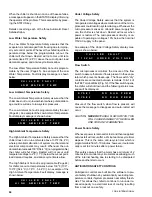
The Low Water Temperature Safety Cut-out is program-
mable by the user (Page 45). An example of the Low
Water Temperature Fault display message is shown
below:
Low Ambient Temperature Safety
The Low Ambient Temperature Safety assures that the
chiller does not run in low ambients where potential dam-
age could result due to low system pressures.
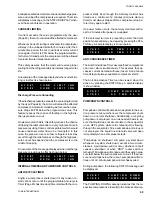
The Low Ambient Cut-out is programmable by the user
(Page 44). An example of the Low Ambient Temperature
Fault display message is shown below:
High Ambient Temperature Safety
The High Ambient Temperature Safety assures that the
chiller does not run in ambients above 130°F (54.4°C)
where potential malfunction of system mechanical and
electrical components may result. Whenever the out-
door ambient exceeds 130°F (54.4°C) (non-programmable)
the chiller will shut down. Restart will not occur until
temperature drops to 2°F (1.1°C) below the cut-out point,
load demand requires, and anti-recycle timers allow.
The High Ambient Cut-out is programmable (Page 44)
for chiller cut-out at temperatures below 130°F (100° -
130°F) [54.4°C (37.8°C - 54.4°C)]. An example of the
High Ambient Temperature Fault display message is
shown below:
C H I L L E R
F A U L T :
L O W
W A T E R
T E M P
C H I L L E R
F A U L T :
L O W
A M B I E N T
T E M P
C H I L L E R
F A U L T :
H I G H
A M B I E N T
T E M P
C H I L L E R
F A U L T :
1 1 5 V A C
U N D E R
V O L T A G E
S Y S # 1
N O
R U N
P E R M
S Y S # 2
N O
R U N
P E R M
Summary of Contents for Millennium YCAJ150
Page 21: ...FORM 150 65 NM4 21 YORK INTERNATIONAL LD02461 FIG 6 ELEMENTARY DIAGRAM Cont d...
Page 22: ...22 YORK INTERNATIONAL ELEMENTARY DIAGRAM...
Page 24: ...24 YORK INTERNATIONAL CONNECTION DIAGRAM FIG 7 CONNECTION DIAGRAM LD02463...
Page 25: ...FORM 150 65 NM4 25 YORK INTERNATIONAL FIG 7 CONNECTION DIAGRAM Cont d LD02462...
Page 30: ...30 YORK INTERNATIONAL FIG 8 SYSTEM WIRING Cont d LD02499...
Page 100: ...100 YORK INTERNATIONAL LD02654 FIG 37B LOUVER BRACKETS INSTALLATION...
Page 103: ...FORM 150 65 NM4 103 YORK INTERNATIONAL LD02656 FIG 39A LOUVER INSTALLATION SIDES...
Page 104: ...104 YORK INTERNATIONAL LD02654 FIG 39B LOUVER BRACKETS INSTALLATION...
Page 108: ...108 YORK INTERNATIONAL FIG 40B CONDENSER COIL LOUVER INSTALLATION FRONT AND BACK LD02659...
Page 110: ...110 YORK INTERNATIONAL FIG 41 REMOTE RESET BOARD LD02666 P1...


