background image

FORM 201.10-NM1

121

YORK INTERNATIONAL

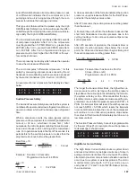
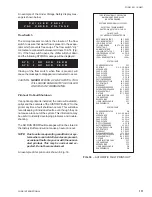
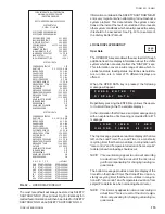
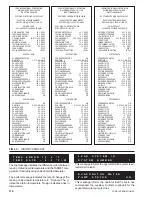
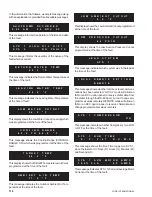
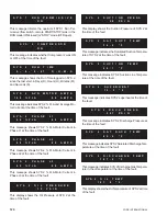
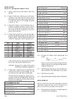
This message indicates that the Liquid Injection Sole-
noid Valve of SYS 2 was either energized (ON) or de-
energized (OFF) at the time of the fault.

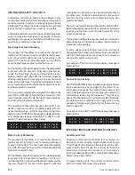
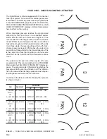
This display indicates the number of pairs of fans on
SYS 2 which were running in the forward direction at the
time of the fault.

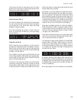
This message indicates whether a pair of fans on SYS 2
were running in the reverse direction at the time of the
fault.

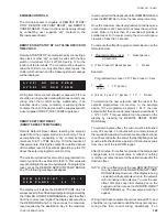
S Y S

2

L I Q U I D

I N J E C T I O N

V A L V E

O F F

S Y S

2

F O R W A R D

F A N S

O N

S Y S

2

R E V E R S E

F A N S

O F F

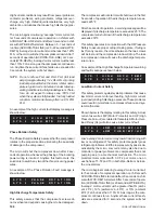
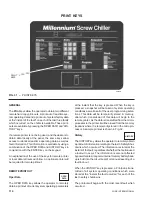
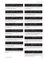
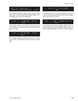
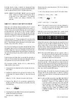
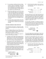
This display informs the operator whether SYS 2 liquid
line solenoid valve was energized (ON) or de-energized
(OFF) at the time of the fault.

This message informs the operator if SYS 1 Run Per-
missive (flow switch, remote START/STOP) was in the
“RUN” mode (ON/closed) or “STOP” mode (OFF/open).

S Y S

2

L I Q

L I N E

O N

S Y S

2

R U N

P E R M I S S I V E

O N

Summary of Contents for Millennium YCAS 216X

Page 1: ...D 200 230 460 575 Models With EPROM 031 01714 001 Standard Brine Metric Models Combined 27960A 28507A M A N U F A C T U R E R C ERTIFIED TO ARI AS C O M P L Y I N G W I T H A RI STANDARD 590 C E N T...

Page 2: ...S 140 246 Weight Distributions 44 YCAS 216X 266X Weight Distributions 48 YCAS 140 246 Wiring Diagrams 52 YCAS 216X 266X Wiring Diagrams 62 Unit Controls and Operation 72 Display Keys 76 Status Key 83...

Page 3: ...ircuit operates correctly GENERAL CHILLER INFORMATION The unit structure is heavy gauge galvanized steel coveredwithabaked onenamel Baserailsareofformed double thickness painted plate steel Units are...

Page 4: ...aracteristics of the unit YC A S 140 X 46 Y D YORK Chiller Design Series Air Cooled Type Start Y WYE Delta X Across the Line Compressor Design Series S Screw Unit Model Voltage Code 17 200 3 60 Class...

Page 5: ...Hz Economized 2 5 Module L 32 x 83 9 50 Hz Economized 3 Module 3 row deep coils 10 60 Hz Economized 3 Module in both systems M 32 x 83 4 row deep coils Gear in System 1 XHS 120 Compressor in System 1...

Page 6: ...00 722 0 130 160 40 52 200 722 0 130 170 40 52 250 803 0 130 180 40 52 250 803 0 130 190 40 52 250 803 0 130 216 40 52 250 803 0 130 216x 40 52 250 803 0 130 236 40 52 250 803 0 130 236x 40 52 250 803...

Page 7: ...2 140 4 4 10 0 12 6 45 5 17 8 54 4 160 4 4 10 0 12 6 45 5 17 8 54 4 170 4 4 10 0 15 8 50 7 17 8 54 4 180 4 4 10 0 15 8 50 7 17 8 54 4 190 4 4 10 0 15 8 50 7 17 8 54 4 216 4 4 10 0 15 8 50 7 17 8 54 4...

Page 8: ...5 722 15 722 15 722 15 722 Cu FIN 17 598 17 598 17 998 17 998 17 998 17 998 REFRIGERANT CHARGE Sys 1 208 208 210 210 210 210 LBS R 22 Sys 2 232 232 235 235 235 235 MODEL YCAS 60Hz 216x 236 236x 246 26...

Page 9: ...OPERATING Al FIN 6950 6950 7131 7131 7131 7131 Cu FIN 7982 7982 8164 8164 8164 8164 REFRIGERANT CHARGE Sys 1 94 94 95 95 95 95 KG R 22 Sys 2 105 105 107 107 107 107 MODEL YCAS 60Hz 216x 236 236x 246 2...

Page 10: ...nit In installations where winter operation is intended and snow accumulations are expected additional unit height must be provided to insure air flow NOTE Reduced clearances may be used due to jobsit...

Page 11: ...FORM 201 10 NM1 11 YORK INTERNATIONAL YCAS 140 246 DIMENSIONS English LD01444 LD01446...

Page 12: ...the unit In installations where winter operation is intended and snow accumulations are expected additional unit height must be provided to insure air flow NOTE Reduced clearances may be used due to...

Page 13: ...FORM 201 10 NM1 13 YORK INTERNATIONAL YCAS 140 246 DIMENSIONS SI LD01440 LD01442...

Page 14: ...it In installations where winter operation is intended and snow accumulations are expected additional unit height must be provided to unsure air flow NOTE Reduced clearances may be used due to jobsite...

Page 15: ...FORM 201 10 NM1 15 YORK INTERNATIONAL YCAS 216X 266X DIMENSIONS English LD01454 LD01454...

Page 16: ...impede air flow to the unit In installations where winter operation is intended and snow accumulations are expected additional unit height must be provided to insure air flow NOTE Reduced clearances...

Page 17: ...FORM 201 10 NM1 17 YORK INTERNATIONAL YCAS 216X 266X DIMENSIONS SI LD01450 LD01448...

Page 18: ...1 1 0 500 231 331 1051 5 0 575 260 400 350 400 350 400 2 6 250 1 1 0 500 184 270 857 4 9 380 414 400 500 700 500 700 2 1 0 500 N A 314 483 1531 5 2 YCAS246 460 332 400 400 500 400 500 2 6 250 1 1 0 5...

Page 19: ...16 1013 5 2 460 224 400 300 350 300 350 2 6 250 1 1 0 500 163 262 838 5 0 575 183 200 225 300 225 250 2 6 250 1 1 0 500 130 204 655 4 9 380 313 400 400 500 400 500 2 6 250 N A 233 401 1272 5 2 YCAS216...

Page 20: ...600 or 2 1 250 YCAS180 460 406 800 450 500 2 2 600 800 3 3 0 500 575 333 400 400 450 2 2 600 400 1 1 600 or 2 1 250 YCAS190 460 432 800 500 600 2 2 600 800 3 3 0 500 575 353 400 400 450 2 2 600 400 1...

Page 21: ...AS236 460 235 398 1261 5 0 235 398 1261 5 0 575 187 311 987 5 0 187 311 987 4 9 YCAS236X 460 231 331 1051 5 0 231 331 1051 5 0 575 184 270 857 4 9 184 270 857 4 9 YCAS246 460 249 398 1261 5 0 249 398...

Page 22: ...450 500 800 3 3 0 500 575 333 400 400 450 400 450 400 1 1 600 or 2 1 250 200 986 1200 1200 1200 1200 1200 N A N A 230 883 1000 1000 1200 1000 1200 1000 3 3 0 500 YCAS190 380 538 600 600 700 600 700 8...

Page 23: ...YCAS170 380 350 450 206 316 1013 5 2 300 400 183 316 1013 5 2 460 300 350 163 262 838 5 0 250 300 144 262 838 5 0 575 225 300 130 204 655 4 9 200 250 115 204 655 4 9 200 N A N A 375 587 1879 10 0 N A...

Page 24: ...450 500 800 3 3 0 500 575 333 400 400 450 400 450 400 1 1 600 or 2 1 250 200 986 1200 1200 1200 1200 1200 N A N A 230 883 1000 1000 1200 1000 1200 1000 3 3 0 500 YCAS190 380 538 600 600 700 600 700 8...

Page 25: ...YCAS170 380 350 450 206 316 1013 5 2 300 400 183 316 1013 5 2 460 300 350 163 262 838 5 0 250 300 144 262 838 5 0 575 225 300 130 204 655 4 9 200 250 115 204 655 4 9 200 N A N A 375 587 1879 10 0 N A...

Page 26: ...26 YORK INTERNATIONAL YCAS 140 246 CHILLER COMPONENTS 27960A POWER PANEL MICRO PANEL LIQUID STOP VALVE FILTER DRYER COMPRESSOR 2 COMPRESSOR 1...

Page 27: ...FORM 201 10 NM1 27 YORK INTERNATIONAL 27960A FAN ORIFICE CONDENSER COIL ECONOMIZER FILTER DRYER LIQUID LINE SOLENOID VALVES TXV S INLET EVAPORATOR HEATER EVAPORATOR OUTLET FILTER DRYER...

Page 28: ...28 YORK INTERNATIONAL 28507A MICRO PANEL POWER PANEL LIQUID STOP VALVE FILTER DRYER COMPRESSOR 2 COMPRESSOR 1 YCAS 216X 266X CHILLER COMPONENTS...

Page 29: ...FORM 201 10 NM1 29 YORK INTERNATIONAL 28508A FAN ORIFICE CONDENSER COIL ECONOMIZER FILTER DRYER INLET EVAPORATOR HEATER EVAPORATOR OUTLET FILTER DRYER...

Page 30: ...OID SUCTION SERVICE VALVE SUCTION PRESSURE TRANSDUCER DISCHARGE MUFFLER OIL DRAIN LINE DISCHARGE SERVICE VALVE DISCHARGE PRESSURE TRANSDUCER OPTIONAL DISCHARGE MUFFLER DISCHARGE PIPING SUCTION SERVICE...

Page 31: ...FORM 201 10 NM1 31 YORK INTERNATIONAL 28512A SYS 1 TXV SYS 1 SIGHT GLASS SYS 1 LIQUID LINE SOLENOID SYS 2 LIQUID LINE SOLENOID SYS 2 TXV SYS 2 SIGHT GLASS...

Page 32: ...Y SOLENOID OIL PRESSURE TRANSDUCER OIL FILTER SUB COOLER ECONOMIZER 15 TON TXV LIQUID SUPPLY SOLENOID 15 TON TXV ECONOMIZER PIPING OIL INJECTION PIPING OIL SEPARATOR 5 TON TXV MOTOR COOLING PIPING LIQ...

Page 33: ...FORM 201 10 NM1 33 YORK INTERNATIONAL 28514A FILTER DRYER LIQUID STOP VALVE...

Page 34: ...34 YORK INTERNATIONAL COMPRESSOR COMPONENTS LD01091 COMPRESSOR SIDE VIEW COMPRESSOR SIDE VIEW MAY BE ON SIDE OR REAR OF MOTOR COVER...

Page 35: ...FORM 201 10 NM1 35 YORK INTERNATIONAL LD01092 NOTE On newer production chillers this valve will not be located on the compressor COMPRESSOR TOP VIEW COMPRESSOR FRONT VIEW COMPRESSOR REAR VIEW...

Page 36: ...36 YORK INTERNATIONAL FIG 2 COMPRESSOR GAS FLOW LD01093 GAS OFF ECONOMIZER HEAT EXCHANGER OIL INJECTION DISCHARGE SUCTION LIQUID INJECTION MOTOR TERMINAL BOX...

Page 37: ...FORM 201 10 NM1 37 YORK INTERNATIONAL LD01285 FIG 3 SCREW CHILLER REFIGERANT FLOW DIAGRAM...

Page 38: ...or incorporates a complete anti friction bearing design for reduced power input and increased reliability Four separated cylindrical roller bearings handleradialloads Angular contactballbearingshandle...

Page 39: ...ides an oil seal against leakage around the rotors toassurerefrigerantcompression volumetricefficiency The oil also provides cooling by transferring much of the heat of compression from the gas to the...

Page 40: ...into the design STARTER Two types of compressor motor starting are available Across the lineandoptionalWye DeltaClosedTransition Starter The Across the line starters will utilize one contactor per co...

Page 41: ...wed to install and start up the chiller HANDLING These units are shipped as completely assembled units containingfulloperatingcharge andcareshouldbetaken to avoid damage due to rough handling The unit...

Page 42: ...selevelwouldbeaproblem Chillernoise is a result of compressor and fan operation Con siderations should be made utilizing noise levels publishedintheYORKEngineeringGuideforthespecific chiller model If...

Page 43: ...o protect against freeze up during low ambient periods and to prevent formation of condensation on lines in warm humid climates 7 Achilledwaterflowswitch eitherbyYORKorothers MUST be installed in the...

Page 44: ...ATION A B C D E F G H YCAS140 2021 1956 1890 1824 2006 1941 1875 1810 YCAS160 2021 1956 1890 1824 2006 1941 1875 1810 YCAS170 2043 1977 1912 1847 2085 2019 1952 1886 YCAS180 2043 1977 1912 1847 2085 2...

Page 45: ...ATOR LOCATION A B C D E F G H YCAS140 2306 2240 2174 2108 2291 2225 2160 2094 YCAS160 2306 2240 2174 2108 2291 2225 2160 2094 YCAS170 2327 2262 2197 2132 2369 2303 2237 2171 YCAS180 2327 2262 2197 213...

Page 46: ...G WEIGHT DISTRIBUTION Kg AND ISOLATOR LOCATION A B C D E F G H YCAS140 917 887 857 827 909 880 850 821 YCAS160 917 887 857 827 909 880 850 821 YCAS170 927 897 867 838 946 916 885 855 YCAS180 927 897 8...

Page 47: ...1039 1009 980 950 YCAS160 1046 1016 986 956 1039 1009 980 950 YCAS170 1056 1026 997 967 1075 1045 1015 985 YCAS180 1056 1026 997 967 1075 1045 1015 985 YCAS190 1056 1026 997 967 1075 1045 1015 985 YC...

Page 48: ...K L YCAS216x 2189 1984 1778 1573 1368 1163 2226 2017 1808 1600 1391 1182 ISOLATOR CP 2 31 CP 2 31 CP 2 31 CP 2 27 CP 2 27 CP 2 27 CP 2 31 CP 2 31 CP 2 31 CP 2 27 CP 2 27 CP 2 27 YCAS236x 2189 1984 17...

Page 49: ...P 2 32 CP 2 32 CP 2 32 CP 2 28 CP 2 28 CP 2 28 CP 2 32 CP 2 32 CP 2 32 CP 2 28 CP 2 28 CP 2 28 YCAS236x 2474 2268 2063 1858 1652 1447 2510 2301 2093 1884 1676 1468 ISOLATOR CP 2 32 CP 2 32 CP 2 32 CP...

Page 50: ...B C D E F G H I J K L YCAS216x 993 900 806 714 621 528 1010 915 820 726 631 536 ISOLATOR CP 2 31 CP 2 31 CP 2 31 CP 2 27 CP 2 27 CP 2 27 CP 2 31 CP 2 31 CP 2 31 CP 2 27 CP 2 27 CP 2 27 YCAS236x 993 9...

Page 51: ...A B C D E F G H I J K L YCAS216x 1122 10209 936 843 749 656 1139 1044 949 855 760 666 ISOLATOR CP 2 32 CP 2 32 CP 2 32 CP 2 28 CP 2 28 CP 2 28 CP 2 32 CP 2 32 CP 2 32 CP 2 28 CP 2 28 CP 2 28 YCAS236x...

Page 52: ...rating and wiring specifications Also refer to cau tions on the following page 5 To stop unit Emergency Stop with contacts other than those shown install the stop contact between 5 and 1 If a stop de...

Page 53: ...ross the relay contactor coil Any contacts con nected to flow switch inputs or BAS inputs on terminals 13 19 or TB3 or any other ter minals must be sup pressed with a YORK P N 031 00808 000 suppressor...

Page 54: ...54 YORK INTERNATIONAL FIG 9 SYSTEM WIRING YCAS 140 246 CONNECTION DIAGRAM SYSTEM WIRING LD01466 D...

Page 55: ...FORM 201 10 NM1 55 YORK INTERNATIONAL FIG 9 CONTINUED YCAS 140 246 COMPRESSOR TERMINAL BOX ACROSS THE LINE START WYE DELTA START LD01466 D LD01459 D...

Page 56: ...ng and wiring specifications Also refer to cau tions on the following page 5 To stop unit Emergency Stop with contacts other than those shown install the stop contact between 5 and 1 If a stop device...

Page 57: ...ross the relay contactor coil Any contacts con nected to flow switch inputs or BAS inputs on terminals 13 19 or TB3 or any other ter minals must be sup pressed with a YORK P N 031 00808 000 suppressor...

Page 58: ...58 YORK INTERNATIONAL FIG 11 CONNECTION DIAGRAM ACROSS THE LINE YCAS 140 246 CONNECTION DIAGRAM ACROSS THE LINE LD01465 D...

Page 59: ...FORM 201 10 NM1 59 YORK INTERNATIONAL FIG 11 CONTINUED LD01465 D...

Page 60: ...60 YORK INTERNATIONAL FIG 12 CONNECTION DIAGRAM WYE DELTA YCAS 140 246 CONNECTION DIAGRAM WYE DELTA LD01458 D...

Page 61: ...FORM 201 10 NM1 61 YORK INTERNATIONAL FIG 12 CONTINUED LD01458 D...

Page 62: ...for annunciations alarm unit malfunction con tacts are rated at 115V 100VA resistive load only and must be suppressed at load by user 6 See installation operation and maintenance manuals when op tion...

Page 63: ...8 000 suppressor across the relay contactor coil Any contacts con nected to flow switch inputs or BAS inputs on terminals 13 19 or TB3 or any other ter minals must be sup pressed with a YORK P N 031 0...

Page 64: ...64 YORK INTERNATIONAL FIG 14 YCAS 216X 266X SYSTEM WIRING YCAS 216X 266X CONNECTION DIAGRAM SYSTEM WIRING LD01207 D...

Page 65: ...FORM 201 10 NM1 65 YORK INTERNATIONAL FIG 14 CONTINUED YCAS 216X 266X COMPRESSOR TERMINAL BOX ACROSS THE LINE START WYE DELTA START LD01207 D LD01203 D...

Page 66: ...nnunciations alarm unit malfunction con tacts are rated at 115V 100VA resistive load only and must be suppressed at load by user 6 See installation operation and maintenance manuals when op tional equ...

Page 67: ...031 00808 000 suppressor across the relay contactor coil Any contacts con nected to flow switch inputs or BAS inputs on terminals 13 19 or TB3 or any other ter minals must be sup pressed with a YORK P...

Page 68: ...68 YORK INTERNATIONAL FIG 16 YCAS 216X 266X CONNECTION DIAGRAM ACROSS THE LINE YCAS 216X 266X CONNECTION DIAGRAM ACROSS THE LINE LD01206 D...

Page 69: ...FORM 201 10 NM1 69 YORK INTERNATIONAL FIG 16 CONTINUED LD01206 D...

Page 70: ...70 YORK INTERNATIONAL FIG 17 YCAS 216X 266X CONNECTION DIAGRAM WYE DELTA YCAS 216X 266X CONNECTION DIAGRAM WYE DELTA LD01202 D...

Page 71: ...FORM 201 10 NM1 71 YORK INTERNATIONAL FIG 17 CONTINUED LD01202 D...

Page 72: ...contacts Compressor starting stopping loading and unloading decisions are performed by the Microprocessor to maintain leaving water temperatures These decisions are a function of temperature deviation...

Page 73: ...ircuit for each compressor is also present to assure that the screw compressorsdonotruninthewrongdirection Allofthese signals are sent to the I O Expansion Board which multiplexes them and then feeds...

Page 74: ...NAL FIG 19 MICROCOMPUTER CONTROL CENTER 27962A I O EXPANSION BOARD POWER SUPPLY BOARD RELAY OUTPUT BOARD 1 RELAY OUTPUT BOARD 2 TB4 TERMINAL BLOCK TERMINALS 13 19 FLOW SWITCH TEMP PWM LEAD LAG ETC MIC...

Page 75: ...DELTA START RESISTORS TB1 115VAC ALARM EVAP PUMP USER CONNECTION TERMINALS 2A SYS 2 TRANSITION CONTACTOR SYS 1 1 2 3 C T S POWER SUPPLY BOARD 27963A 1 CR 2 TR SYS 2 4 5 6 C T S POWER SUPPLY BOARD 2 CR...

Page 76: ...Messages may show characters indicating greater than or less than These characters indicatetheactualvaluesaregreaterthanorlessthanthe limit values which are being displayed If a message is required to...

Page 77: ...e In the case of maximum limits or values exceeding them will cause a sign to appear NOTE Minimum and maximum values may change as software EPROM revisions are made SYSTEM 1 PRESS TEMP MIN LIMITS MAX...

Page 78: ...n EMS system connected to the micro This display shows the current limiting that may be in effect from these devices This display indicates the ISN programmed value of FLA of the lead compressor where...

Page 79: ...the next display is automatically indexed When all messages are displayed thedisplaymessagewillautomaticallychange to show a chiller STATUS message just as if the STATUS key was pressed Refer to Table...

Page 80: ...t out to be programmable from 8 36 FandtheSuctionPressureCut outfrom20 70PSIG SWITCH 2 OPEN This mode fixes the low ambient cut out at 25 F and must be selected when a Low Ambient Kit is NOT installed...

Page 81: ...sion valves CLOSED This switch is presently disabled In the future it will allow selection of control from either thermal expansion valves or electronic expansion valves SWITCH 5 OPEN Display messages...

Page 82: ...th compressors are shut down the micro will start the first available compressorinanefforttomaintaincontroloftemperature as soon as possible SWITCH 8 OPEN This switch position MUST be selected if the...

Page 83: ...Thismessageinformstheoperatorthatthe UNIT switch on the Control Panel is in the OFF position which will not allow the chiller to run TheDAILYSCHEDULESHUTDOWNmessageindicates thatthedailyscheduleprogra...

Page 84: ...opped 60 PSIG below the threshold The Suction Temperature Limiting Message indicates that the microprocessor is in the water temperature control mode and is sensing that the saturated suction temperat...

Page 85: ...the system switch on the Microprocessor Board for the respective system is in the OFF position The switch for System 1 and System 2 must be in the ON position for the systems tooperate SwitchesforSyst...

Page 86: ...M B I E N T T E M P S Y S 1 H I G H O I L D I F F S Y S 2 H I G H O I L D I F F S Y S 1 L O W O I L D I F F S Y S 2 L O W O I L D I F F the type of refrigerant selected on the S1 dip Switches on the...

Page 87: ...in the SET SCHEDULE HOLIDAY display Advance Day Key The ADVANCE DAY key advances the day when the SET TIME display is being programmed The day is nor mally advanced to correspond to the current day of...

Page 88: ...ed Programmable values not password protected are identified by the presenceofthecursorunderthefirstdigitofthenumerical value Non password protected values may be keyed in by simply typing a new value...

Page 89: ...ypically chillers with air cooled condensers should have the cut out set at 395 PSIG 275 PSIG for R134a To program the DISCHARGE CUT OUT access the password protected values as described previously Ke...

Page 90: ...ing By unloading the compressors at high discharge pressures the chiller is allowed to continue to run automatically at reduced capacity until the dirty condenser coils can be attended to When the unl...

Page 91: ...ion could occur under low flow conditions or if the MicroPanelSetpointvaluesareimproperlyprogrammed Anytime the leaving chilled liquid temperature water or glycol drops below the cut out point the chi...

Page 92: ...efficient condition for operating the chiller system However keep in mind that once the lag compressor is started equalized loading at part load is always maintained by the microprocessor even with t...

Page 93: ...351 PSIG 72 203 PSIG for R134a After the first pair or trio of reverse fans are brought on discharge pressure must rise 20 PSIG above the FAN CNTRL DSCH PRESS SETPOINT before a second pair or trio of...

Page 94: ...key Thenewvaluewillbeenteredintomemoryandthedisplay will advance to the next programmable value Once on the liquid injection will turn off 20 F below the ON temperature SYSTEM 1 COND TEMP If loading u...

Page 95: ...load the 15 ton TXV solenoid is shut off to prevent feeding excessive liquid to the compressor As load rises the 15 ton TXV solenoid valve is energized providing additional subcooling needed for effic...

Page 96: ...0 is selected the display will return to the STATUS display If a 1 is selected the display will momentarily display the message shown below before returning to the STATUS display A list of the default...

Page 97: ...ption of the operation and programming follows PROGRAMMING CHILLED LIQUIDTEMP RANGE Chilled Liquid Temp Range When the CHILLED LIQUID TEMP RANGE key is pressed one of the following messages will be di...

Page 98: ...Target HLWT LLWT Zone 4 From the example Neutral 44 F 46 F 42 F Zone 4 Neutral 44 F 1 F Zone In the example above with a CR 42 0 to 46 0 F the TARGET temperature will be 44 0 F with a Neutral Zone of...

Page 99: ...solenoid allowing oil pressure to move the slide valve to increase capacity Every 10 120 seconds the micro will pulse the slide valve with a 0 4 5 second pulse The time between pulses will be a functi...

Page 100: ...sor will start regardless of the programmed Start after 5 minutes of operation This will occur whenever the lead compressor cannot bring the LWT to within 2 0 F of the high end of the CONTROL RANGE CR...

Page 101: ...ws the user to either allow the lead compressor to fully load before the lag compressor is started or start the lag compressor is fully loaded Key in a start point and press the ENTER key A sample dis...

Page 102: ...ate to a minimum of 20 FLA of the lead compressor Therefore the LAG COMPRES SOR START MINUS THE LAG COMPRESSOR DIF FERENTIAL OFF cannot be less than 20 or an OUT OF RANGE message will appear To progra...

Page 103: ...dless of the programmed Start after 5 minutes of operation This will occur whenever the lead compressor cannot bring the LWT to within 2 0 F of the high end of the CONTROL RANGE CR Once the lag compre...

Page 104: ...re chiller on a Low WaterTemp Fault This will occur under 2 conditions 1 The leaving chilled liquid temperature falls below the low end of the CONTROL RANGE CR for 37 sec onds 2 The leaving chilled li...

Page 105: ...lag compressor will both load share until the Slide Valve of the lead compressor drops to 20 70 50 20 At this point the micro will unload only the lag compres sor until it reaches a point at which the...

Page 106: ...ts which could open a relief valve or other pressure relief device caus ing refrigerant loss This safety is a back up for the mechanical High Pres sure Cut out in the system The Discharge Pressure Saf...

Page 107: ...0 10 3 x 44 13 2 PSIG 100 A close examination of the formula indicates the suction pressure cut out increases with time for the first 270 sec onds after the safety becomes active After 270 seconds the...

Page 108: ...ion a warning message will be displayed if discharge temperature exceeds 225 F The compressor will shut down if the discharge temperature exceeds 230 F This safety operates in conjunction with the Oil...

Page 109: ...mpressor current so Relay Dial Setting 1 1 x 0 58 x RLA 350 Anytime the External Motor Overload Relay trips a manual reset of the device is required to restart the com pressor After the first fault th...

Page 110: ...potential dam age could result due to low system pressures It can also be used to shut down the chiller at a temperature where continued running of the chiller is not economical as compared to the us...

Page 111: ...ple of this print out is shown in Fig 30 C H I L L E R F A U L T V A C U N D E R V O L T A G E S Y S 1 N O R U N P E R M S Y S 2 N O R U N P E R M FIG 30 AUTOMATIC FAULT PRINT OUT YORKINTERNATIONALCOR...

Page 112: ...the first 60 seconds of operation the unloading safety is ignored After 60 seconds of operation if motor cur rent exceeds the Current Limit Setpoint programmed by the user Page 90 the micro will unloa...

Page 113: ...er assure that liquid does not accumulate in the evapo rator On shutdown the Compressor SlideValve Unload Solenoid will be energized to unload the compressor and the Liquid Line Solenoid and Economize...

Page 114: ...nt that the key is pressed When the key is pressed a snapshot will be taken of system operating conditions as well as all of the user programming selec tions This data will be temporarily stored in me...

Page 115: ...OP 00 00AM WED START 00 00AM STOP 00 00AM THU START 00 00AM STOP 00 00AM FRI START 00 00AM STOP 00 00AM SAT START 00 00AM STOP 00 00AM HOL START 00 00AM STOP 00 00AM Information contained in the SAFET...

Page 116: ...49 1 DEGF LEAVINGWATERTEMP 42 9 DEGF LOW WATER CUTOUT 8 0 DEGF COOLINGRANGE 42 0 TO 44 0 DEGF TARGETTEMP 43 0 DEGF AMBIENTAIRTEMP 70 0 DEGF LOW AMBIENT CUTOUT 25 0 DEGF LOW PRESSURE CUTOUT 36 PSIG LEA...

Page 117: ...which occurred Informa tion contained in the micro s SAFETY SHUTDOWN buff ers is very important when attempting to troubleshoot a system problem This data reflects system conditions at the instant th...

Page 118: ...message shows whether remote or local communi cations has been selected LOCAL mode will allow an ISN or an RCC option panel to receive chiller data from the chiller through the RS 485 port but not cha...

Page 119: ...time of the fault This message indicates that the Liquid Injection Sole noid Valve of SYS 1 was either energized ON or de energized OFF at the time of the fault This display indicates the number of p...

Page 120: ...his message indicates SYS 2 Suction Line Tempera ture at the time of the fault This message indicates SYS 2 superheat at the time of the fault This message indicates SYS 2 Discharge Pressure at the ti...

Page 121: ...r of fans on SYS 2 were running in the reverse direction at the time of the fault S Y S 2 L I Q U I D I N J E C T I O N V A L V E O F F S Y S 2 F O R W A R D F A N S O N S Y S 2 R E V E R S E F A N S...

Page 122: ...lize the schedule feature the SET SCHEDULE HOLIDAY can be programmed to run the chiller on demand as long as the UNIT and SYS switches are ON Typical display messages will be shown which apply to each...

Page 123: ...ys selected as a HOLIDAY After programming AM PM or if no change is required begin keying in the required date the cursor will auto matically skip to the first digit of the date day when a number key...

Page 124: ...erventiontoerasethesched ule after the holiday passes If an error is made while programming or a change is required press CANCEL This will clear the programmed Holiday days The schedule can then be re...

Page 125: ...US message is displayed indicating that the system does not have a Run Permissive signal An example of this message is shown below NOTE This message will not appear if the Anti recycle or Anti coincid...

Page 126: ...n YORK will not be liable for damages LEAD LAG COMPRESSOR SELECTION ThechillermaybesetupforAUTOorMANUALLead Lag This is accomplished by properly configuring the S1 Dip Switches on the Microprocessor B...

Page 127: ...setpointas possible The dry contact for manual lead lag selection is wired into terminals 13 and 19 of the TB3 Terminal Block The location of these contacts is shown in Fig 38 MEMORYBATTERYBACK UP The...

Page 128: ...n Fig 39 The part number of the RTC Chipis031 00955 000 COMPRESSORHEATER The Compressor Heater in each compressor will be ON for the first five minutes after the compressor is shut down Then the heate...

Page 129: ...required by the application Key in the maximum reset required for the application after REM RANGE and press the ENTER Key to store the new value in memory Once the maximum reset is programmed it will...

Page 130: ...offset See the formula below Offset Offset 100 4 CalculatethePulseWidth PW insecondsrequiredby utilizing the following formula PW seconds Offset x 20 1 Show below is an example where 75 FLA is Desire...

Page 131: ...in the forward direction This is the same pair of fans that originally ran in the reverse direction The first pair of forward fans will also continue to run The point at which each pair of fans cycle...

Page 132: ...art in the forward direction This is the same trio of fans that originally ran in the reverse direction The first trio of forward fans will also continue to run The point at which each trio of fans cy...

Page 133: ...om or top sight glass with the compressor off If it is necessary to add oil connect a YORK oil pump to the charging valve on the oil separator but do not tighten the flare nut on the delivery tubing W...

Page 134: ...____________________ Dischg Press Cut out _______________ PSIG kPa Low Amb Cut out ______________________ F C HighAmbCut out ______________________ F C DischPressUnld ___________________PSIG kPa AvgCu...

Page 135: ...by recording the temperature of the liquid line at the outlet of the condenser and subtracting it from the recorded liquid line pressure at the liquid stop valve con vertedtotemperaturefromthetempera...

Page 136: ...n adjust ments for the system and the thermal expansion valve to respond and settle out Assure that superheat is set between 10 15 F q 1 Record the motor gas temperature economizer pressure economizer...

Page 137: ...heck for cooling demand as well as check to see if any system safeties are exceeded If all conditions allow for start the lead compressor will start unloaded Coincident with the start the programmable...

Page 138: ...load on the board NOTE ContactYORK Service before Replacing circuit Boards NO RUN PERMISSIVE 1 No chilled liquid flow 1 Check chilled liquid flow 2 Flow switch improperly 2 Check that the flow switch...

Page 139: ...tor protector wiring and motor problems Assure the motor protector is not tripped due to a tripped mechanical high pressure switch 3 Defective Relay Output 3 Relay Output Board Board defective CONTACT...

Page 140: ...ctive suction pressure 6 Replace transducer or transducer or faulty wiring repair wiring HIGH DISCHARGE 1 Condenser fans not 1 Check fan motor fuses PRESSURE FAULT operating or operating and contactor...

Page 141: ...parator 5 Add oil to separator HIGH OIL TEMP 1 Dirty oil cooling coil 1 Clean oil cooling coil 2 Faulty oil temp 2 Check replace valve diverting valve 3 Fault oil temp sensor 3 Check replace oil temp...

Page 142: ...d ambient a drop in temperature incorrectly by thermistor temp is within or 15 F of a thermometer placed next to the OAT sensor 3 Fans rotating backwards 3 Air flow from forward fans must be up Correc...

Page 143: ...3 Compare the display with temperature sensor a thermometer Should be within or 2 degrees Lack of Cooling Effect 1 Fouled evaporator surface 1 Contact the localYORK Low suction pressure service repre...

Page 144: ...336 2 76 7 170 338 0 77 2 171 339 8 77 8 172 341 6 78 3 173 343 4 78 9 174 345 2 79 4 175 347 0 80 0 176 348 8 80 6 177 350 6 81 1 178 352 4 81 7 179 354 2 82 2 180 356 0 82 8 181 357 8 83 3 182 359...

Reviews: