FORM 201.10-NM1
93
YORK INTERNATIONAL
load drops, both compressors will unload to 60%. At this
point, only the lag compressor will be unloaded as
demand drops. It will unload until it reaches a point at
which the micro determines it is fully unloaded and load
does not require its continued operation and the
compressor will be cycled off.
A minimum % point is built into the micro to only allow load
sharing to operate to a minimum of 20% of the lead
compressor. Therefore the LAG COMPRESSOR START
POINT % minus the LAG COMPRESSOR DIFFEREN-
TIAL OFF % cannot be less than 20% or an out of range
message will appear.
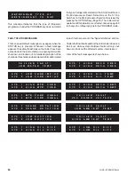
To program the LAG COMPRESSOR DIFFERENTIAL
OFF %, key in the desired value and press the “ENTER”
key. The new value will be entered into memory and the
display will advance to the next user programmable value.
This value is not password protected and can be
programmed anytime the PROGRAM key is pressed.
The micro will accept a range of programmable values
between 0 - 50% for this operating control, provided the
LAG COMPRESSOR START POINT % minus the LAG
COMPRESSOR DIFFERENTIAL OFF % does not equal
less than 20%.
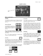
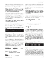
FAN CONTROL DISCHARGE PRESSURE SETPOINT
The FAN CNTRL DSCH PRESS SET POINT is
programmable to allow the operator to program the
discharge pressure at which the first pair or trio of fans
starts. The first pair or trio of fans will run in the reverse
direction. Selection of the discharge pressure should be
done keeping in mind oil return and proper TXV operation.
Generally, the recommended point of fan starting is 230
PSIG. Too low of a setting will cause low discharge
pressures which in turn causes oil return problems and
TXV operation problems. Both of these can lead to
catastrophic compressor failure.
To program the FAN CONTROL DISCHARGE
PRESSURE SETPOINT, access the password
protected values as described previously. Key in the
pressure setpoint and press the ENTER key. The new
value will be entered into memory and the display will
advance to the next user programmable value.
The micro will accept a range of programmable values
from 149 - 351 PSIG (72 - 203 PSIG for R134a).
After the first pair or trio of reverse fans are brought on,
discharge pressure must rise 20 PSIG above the FAN
CNTRL DSCH PRESS SETPOINT before a second pair
or trio of fans (first pair or trio of forward fans) will be
brought on in the forward direction.
The pair or trio of reversing fans will turn off at this point.
After discharge pressure rises 40 PSIG above the FAN
CNTRL DSCH PRESS SETPOINT, the second pair or
trio of forward fans will turn on and operate. These are the
reversing fans operating in the forward direction. The first
pair or trio of forward fans will also continue to run.
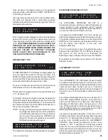
FAN ON / OFF PRESS DIFF
The FAN ON/OFF PRESS DIFF determines the “OFF”
pressure at which each pair or trio of fans will cycle off. If
a differential of 50 PSIG is selected, the second pair or trio
of forward fans that cycled on (Example: 270 PSIG) will
cycle off when discharge pressure drops 50 PSIG below
the “ON” pressure (Example: 220 PSIG). The first pair or
trio of forward fans to start (Example: 250 PSIG) will cycle
off at 50 PSIG below the on pressure (Example: 200
PSIG). When this pair or trio of fans cycles off, the
reversing fans will not come on until the pressure reaches
the FAN CONTROL DISCHARGE PRESSURE
SETPOINT (Example: 230 PSIG).
If the reversing fans are operating, they too will turn off on
a pressure drop. In the example above, if the reversing
fans turned on at 230 PSIG and are operating, they would
turn off at 180 PSIG.
A FAN ON/OFF PRESSURE DIFFERENTIAL of 50 - 70
PSIG is recommended.
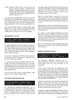
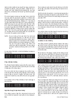
SYSTEM 1 MOTOR CURR
SYSTEM 1 MOTOR CURR allows the operator to display
the approximate current that the motor is drawing by
pressing the Display key labeled % MOTOR CURRENT.
SYSTEM 1 MOTOR CURR also allows the motor current
to be programmed at 100% full load to permit the micro to
determine the approximate slide valve position when
controlling loading/unloading. This is important to allow
load sharing.
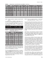
Select the actual current at 100% load by selecting the
chiller model and voltage from Table 2 and its
corresponding AMPS at 100% RLA. Multiply RLA x 1.2 to
determine 100% FLA current.
F A N
C N T R L
D S C H
P R E S S
S E T
P O I N T
=
2 3 0
P S I G
F A N
O N / O F F
P R E S S
D I F F
=
5 0
P S I G
S Y S T E M
1
M O T O R
C U R R
1 8 3
A M P S
=
1 0 0
% F L A
Summary of Contents for Millennium YCAS 216X
Page 11: ...FORM 201 10 NM1 11 YORK INTERNATIONAL YCAS 140 246 DIMENSIONS English LD01444 LD01446...
Page 13: ...FORM 201 10 NM1 13 YORK INTERNATIONAL YCAS 140 246 DIMENSIONS SI LD01440 LD01442...
Page 15: ...FORM 201 10 NM1 15 YORK INTERNATIONAL YCAS 216X 266X DIMENSIONS English LD01454 LD01454...
Page 17: ...FORM 201 10 NM1 17 YORK INTERNATIONAL YCAS 216X 266X DIMENSIONS SI LD01450 LD01448...
Page 33: ...FORM 201 10 NM1 33 YORK INTERNATIONAL 28514A FILTER DRYER LIQUID STOP VALVE...
Page 37: ...FORM 201 10 NM1 37 YORK INTERNATIONAL LD01285 FIG 3 SCREW CHILLER REFIGERANT FLOW DIAGRAM...
Page 59: ...FORM 201 10 NM1 59 YORK INTERNATIONAL FIG 11 CONTINUED LD01465 D...
Page 61: ...FORM 201 10 NM1 61 YORK INTERNATIONAL FIG 12 CONTINUED LD01458 D...
Page 69: ...FORM 201 10 NM1 69 YORK INTERNATIONAL FIG 16 CONTINUED LD01206 D...
Page 71: ...FORM 201 10 NM1 71 YORK INTERNATIONAL FIG 17 CONTINUED LD01202 D...


