134
YORK INTERNATIONAL
INITIAL START-UP
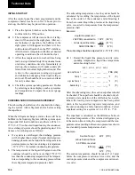
After the control panel has been programmed and the
compressor heater has been on for 24 hours prior to
start-up, the chiller may be placed into operation.
q
1. Place the System Switches on the Microproces-
sor Board to the ON position.
q
2. The compressor will start and a flow of refrig-
erant will be noted in the sight glass. After sev-
eral minutes of operation, the bubbles in the
sight glass will disappear and there will be a
solid column of liquid when the TXV stabilizes.
After the water temperature stabilizes at desired
operating conditions, the oil should be clear.
q
3. Allow the compressor to run a short time, being
ready to stop it immediately if any unusual noise
or adverse conditions develop. Immediately at
start-up, the compressor will make sounds dif-
ferent from its normal high pitched sound. This
is due to the compressor coming up to speed
and lubrication changing from liquid refriger-
ant to oil. This should be of no concern and lasts
for only a short time.
q
4. Check the system operating parameters. Do this
by selecting various displays such as pressures
and temperatures. Compare these to test gauge
readings.
CHECKING SUBCOOLING AND SUPERHEAT
The subcooling should always be checked when charg-
ing the system with refrigerant and/or before setting
the superheat.
When the refrigerant charge is correct, there will be no
bubbles in the liquid sight glass with the system oper-
ating under full load conditions, and there will be 10 -
15°F (6 - 8°C) subcooled liquid leaving the condenser.
An overcharged system should be guarded against. Evi-
dences of overcharge are as follows:
a.
If a system is overcharged, the discharge pressure
will be higher than normal. (Normal discharge/con-
densing pressure can be found in the refrigerant tem-
perature/pressure chart; use entering air temperature
+30°F (17°C) for normal condensing temperature.
b. The temperature of the liquid refrigerant out of the
condenser should be not be more than 15°F (8°C)
less than the condensing temperature (The tempera-
ture corresponding to the condensing pressure from
the refrigerant temperature/pressure chart).
The subcooling temperature of each system should be
calculated by recording the temperature of the liquid
line at the outlet of the condenser and subtracting it
from the recorded liquid line pressure at the liquid stop
valve, converted to temperature from the temperature/
pressure chart.
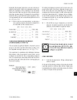
Example:
Liquid line pressure =
202 PSIG converted to
102°F (39°C)
minus liquid line temp.
- 87°F (31°C)
SUBCOOLING =
15°F (8°C)
The subcooling should be adjusted to 12 - 15°F (7 - 8°C).
q
1. Record the liquid line pressure and its corre-
sponding temperature, liquid line temperature
and subcooling below:
SYS 1 SYS 2
SYS 3 SYS 4
Liq Line Press =
____
____
____
____ PSIG (kPa)
Temp =
____
____
____
____ °F
(°C)
Liq Line Temp =
____
____
____
____ °F
(°C)
Subcooling =
____
____
____
____ °F
(°C)
After the subcooling is set, the suction superheat should
be checked. The superheat should be checked only af-
ter steady state operation of the chiller has been estab-
lished, the leaving water temperature has been pulled
down to the required leaving water temperature, and
the unit is running in a fully loaded condition. Correct
superheat setting for a system is 10 - 12°F (6 - 7°F).
The superheat is calculated as the difference between
the actual temperature of the returned refrigerant gas
in the suction line entering the compressor and the tem-
perature corresponding to the suction pressure as shown
in a standard pressure/temperature chart.
Example:
Suction Temp =
46°F (8°C)
minus Suction Press
60 PSIG converted
to Temp
- 34°F (1°C)
12°F (7°C)
The suction temperature should be taken 6" (13 mm)
before the compressor suction service valve, and the
suction pressure is taken at the compressor suction ser-
vice valve.
Technical Data
Summary of Contents for MILLENNIUM YCAS 250
Page 61: ...61 YORK INTERNATIONAL FORM 201 18 NM3 This page intentionally left blank 7...
Page 65: ...65 YORK INTERNATIONAL FORM 201 18 NM3 LD04179 7...
Page 79: ...79 YORK INTERNATIONAL FORM 201 18 NM3 This page intentionally left blank 7...
Page 83: ...83 YORK INTERNATIONAL FORM 201 18 NM3 This page intentionally left blank 7...
Page 87: ...87 YORK INTERNATIONAL FORM 201 18 NM3 LD04268 7...
Page 195: ...195 YORK INTERNATIONAL FORM 201 18 NM3 This page intentionally left blank...

