2
YORK INTERNATIONAL
USING THIS BOOK
The “Theory of Operation” section provides an overview
of the unit control provided by the MILLENNIUM CON-
TROL CENTER. Unit control is described and operating
and status messages that are displayed on the Control
Center display are highlighted.
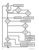
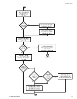
The “Operation Flow Chart” can be used as a quick
reference of unit control providing safety, cycling and
warning messages and the inputs or thresholds that
produce these shutdowns and messages. Also, the
sequence of events of all safety and cycling shutdowns
and respective reset thresholds are detailed in sepa-
rate flow charts. To use this flow chart, start at the
beginning and read down. The starting sequence is
described, followed by the system parameters that are
monitored (checked) by the Control Center. The Con-
trol Center’s response to each of these checks is de-
scribed adjacent to the check. The Control Center is
programmed to respond in a certain way to each of the
monitored parameters. Pressures and temperatures
that exceed safety thresholds result in a safety shut-
down. Other Control Center inputs that are open or
closed cause safety or cycling shutdowns. If a shut-
down is initiated, the displayed message is shown. The
user is directed to a safety or cycling shutdown flow-
chart that details the sequence of events of the shut-
down and allowable restart thresholds. That flowchart
then returns the user to the main flowchart. Not all
responses cause shutdowns. Some cause the Control
Center to limit operation by shutting down a pump or
inhibit unit loading. These responses are shown adja-
cent to the check along with any warning message.
The “Control Center” and “Operation” section describes
how to operate the Control Center. The functions of the
major grouping of keys are described. It also describes
how to display system parameters such as tempera-
tures and pressures. Finally, each system setpoint is
explained along with how to display the programmed
system setpoints.
In the “Programming the Millennium Control Center” sec-
tion, the operator is instructed in how to program sys-
tem setpoints.
The “Service Keys” section describes the function and
operation of the service keys. The service keys are pro-
vided for use by the service technician or operator to
have manual control of certain unit functions.
The “Operating Modes” section describes the various
operating modes and how to change the operating
modes. The “Unit Switch” section describes how to start
and stop the unit.
The “Display Messages” section is a listing of all the
operating, status, safety and cycling shutdown mes-
sages that are displayed on the keypad display. The
meaning of each message is described in detail; in-
cluding the system event threshold that caused the
message to be displayed and the event or threshold
that causes the message to be cleared.
THEORY OF OPERATION
OVERVIEW
An understanding of the operation of a single-stage
absorption chiller requires a review of the chiller’s mi-
cro panel wiring diagram, power panel wiring diagram,
the keypad, and the description which follows. Major
system components include the solution pump (re-
placed by two pumps – absorber and generator on 50
Hz Models YIA-10E3 – YIA-14F3 units equipped with
Franklin pumps – that are individually controlled); refrig-
erant pump; purge (vacuum) pump and purge solenoid
valve; manual purge valve; steam or hot water control
valve feedback potentiometer and steam or hot water
stop valve; generator shell pressure transducer, strong
solution temperature sensor, high pressure and high tem-
perature cut-out switches; steam supply pressure trans-
ducer (steam units only); steam or hot water supply tem-
perature sensor; automatic decrystallization (ADC)
temperature sensor; refrigerant temperature-sensor;
refrigerant temperature leaving the condenser sensor;
low refrigerant temperature cut-out switch; refrigerant
level float switch (1F); motor coolant level float switch
(2F) (units equipped with Franklin pumps only); refriger-
ant level float switch (3F) (units equipped with Buffalo
pumps only); chilled and condenser water flow switches
(condenser water flow switch furnished by others); chilled
and condenser water pumps (by others); inlet and outlet
temperature sensors for chilled and condenser water cir-
cuits; refrigerant (unloader) solenoid valve; stabilizer re-
frigerant solenoid valve; motor coolant solenoid valve
(units equipped with Franklin pumps only); and steam
condensate drain solenoid valve.
An absorption chiller functions by heating a lithium bro-
mide solution to generate hot refrigerant vapor and
strong solution (64.5% lithium bromide).
Summary of Contents for MILLENNIUM YIA-HW-14F3
Page 116: ...YORK INTERNATIONAL 115 FORM 155 16 O3 NOTES...
Page 117: ...116 YORK INTERNATIONAL NOTES...


