88
YORK INTERNATIONAL
CONTROL CENTER
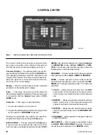
FIG. 1 – MICROCOMPUTER CONTROL CENTER KEYPAD
The Control Center front panel layout consists of five
key groups, one switch, and a I-line by 40-character al-
pha numeric vacuum fluorescent display (see Fig. 1).
Character Display – The alphanumeric vacuum fluo-
rescent display is located to the right of the STATUS key.
All messages, parameters, setpoints, and data can be
viewed at this location. The main communications be-
tween the operator or service technician and the Con-
trol Center occur on this display.
Display – Provide a direct readout of each monitored
parameter on the alphanumeric display.
Entry – These keys are used to enter the values for
this operator programmed setpoints. These keys are used
in conjunction with the Setpoint keys while in PRO-
GRAM mode.
Setpoints – These keys are used as follows:
1. To view each setpoint, in any mode or
2. To select the individual setpoints that are programmed
by the operator in PROGRAM mode only.
Pressing the appropriate key enables the operator to
program that setpoint by pressing the Entry keys.
ACCESS CODE – This key, along with the Entry keys,
is used to enter the 4-digit access code. Entry of the
correct access code allows the operator access to PRO-
GRAM mode, where the operator can change Setpoints
or OPERATING modes (LOCAL, REMOTE, or SER-
VICE). This access code provides security. It prevents
tampering by an authorized personnel.
PROGRAM – Permits the operator to change setpoints
and operating modes (LOCAL, REMOTE, SERVICE).
MODE – Permits operator to check what mode the
Control Center is presently in. Also, used with the PRO-
GRAM key to change operating modes. The modes are
as follows:
1. LOCAL – Allows manual unit start from the UNIT
rocker switch on the front panel. Also allows certain
cycling inputs from remote devices to start and stop
unit.
2. REMOTE – Allows remote start and stop of unit. Also
allows remote reset of leaving water temperature
(chilled or hot) and remote load limit setpoints.
3. SERVICE – Allows manual control of burner or steam
valve and pumps. Allows use of the WARNING RE-
SET key.
4. PROGRAM – Allows operator to change modes and
program setpoints.
UNIT SWITCH – This 3-position rocker switch is used
for START, RUN, STOP-RESET functions. This switch
cannot be used to start the unit in REMOTE mode.
28342A(D)
Summary of Contents for MILLENNIUM YIA-HW-14F3
Page 116: ...YORK INTERNATIONAL 115 FORM 155 16 O3 NOTES...
Page 117: ...116 YORK INTERNATIONAL NOTES...

