background image

FORM 155.21-O1 (615)

27

JOHNSON CONTROLS

2

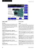
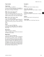
Login

Access level required:


View


This key is displayed when the user is NOT logged in. 

Pressing the login key will bring up a login screen, al

-

lowing OPERATOR and SERVICE access level.

Logout 

Access Level Required: 

OPERATOR or SERVICE

This key is displayed when a user is logged in at any 

level other than 

VIEW

. Pressing it will return the access 

level to 

VIEW

.

Print 

Access Level Required: 

VIEW

Use this key to generate a hard-copy report of the present 

system status. This provides a snapshot of the primary 

operating conditions at the time the key is pressed. 

Warning Reset 

Access Level Required:

 OPERATOR or SERVICE

Use of this key acknowledges a warning condition and 

resets the message display associated with it, if the in-

stigating condition is no longer present.

Soft Shutdown

Access Level Required:

 OPERATOR

Use of this key initiates a gradual shutdown of the chiller, 

closing the steam/hot water control valve according to 

the programmable rampdown schedule prior to exiting  

system run status.

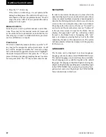
Navigation

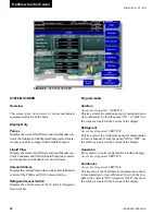
Evaporator / Absorber

Causes an instant return to a detailed view of all Evapo-

rator and Absorber parameters, including the program-

mable Leaving Chilled Liquid Setpoints.

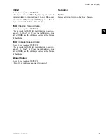
Generator / Condenser

Causes an instant return to a detailed view of all Gen-

erator and Condenser parameters, including Generator 

pressure, Steam temperature and pressure, and Solution 

temperature and concentration.

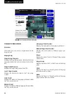
System

Causes an instant return to a detailed view of the status 

of System Pumps, Liquid Flow details, Solenoid Valves, 

and Level Switches. Manual operation of these devices 

is from here.

Purge

Causes an instant return to a 

detailed view of Purge 

Pump, Valve  status  &  Purge Tank  pressures, Auto-

Manual purge counters, & Purge mode. Purge trend is 

accessed from here.

Control Valve

Causes an instant return to a detailed view of Steam 

/  Hot Water  Control Valve  specifics  and  associated 

calibration.

Setpoints

Causes an instant return to a single location to program 

the most common system setpoints. It is also the gateway 

to many of the general system setup parameters such as 

Date/Time, Display Units, Scheduling, Printer Setup, 

etc.

Sales Order

Causes an instant return to a detailed view for the spe-

cifics of the Absorption Unit, including Model, Serial 

number, & capacities. Configuration can be accessed 

from here in SERVICE access.

History

Causes an instant return to a screen that provides ac-

cess to a snapshot of system data at each of the last 10 

safety shutdowns, cycling shutdowns, start inhibits and 

warning conditions. Graphic system trending is accessed 

from here.

Summary of Contents for OPTIVIEW YIA D

Page 1: ...AGE YIA ABSORPTION CHILLERS WITH OPTIVIEWTM CONTROL CENTER Supersedes Form 155 21 O1 410 Form 155 21 O1 615 YIA MOD D SINGLE STAGE STEAM HOT WATER WITH OPTIVIEWTM CONTROL CENTER 1A1 through 14F3 LD137...

Page 2: ...individual shall also be familiar with and comply with all applicable governmental standards and regulations pertaining to the task in question SAFETY SYMBOLS The following symbols are used in this do...

Page 3: ...Hot Water UNIT TYPE YORK IsoFlow Absorption Chiller CHANGEABILITY OF THIS DOCUMENT In complying with YORK Johnson Controls policy for continuous product improvement the information contained in this...

Page 4: ...atus Messages 63 SECTION 3 PRINTERS 65 Printer Setup 66 Control Center Setup 67 Downloading Histories to a Laptop 71 TABLE OF CONTENTS LIST OF FIGURES FIGURE 1 MODELYIAOPTIVIEW CHILLER 5 FIGURE 2 FLOW...

Page 5: ...ercury a relatively high vacuum The vacuum allows water the refrigerant to boil at a temperature below that of the liquid being chilled Chilled liquid entering the evaporator can be cooled for air con...

Page 6: ...proving efficiency Likewise the cooler the solution is going to the Absorber the less heat that needs to be removed by the cooling tower Therefore the heat exchanger preheats the solution going to the...

Page 7: ...Disk Although IsoFlow absorption units operate at less than atmospheric pressure a vacuum if certain safeties fail and or incorrect valves are closed the unit could experi ence higher pressures in ce...

Page 8: ...rtain by weight of dissolved lithium bromide LiBr Corrosion inhibi tors are also added to the solution to reduce the internal corrosion rates in the unit 2SOL Stabilizer refrigerant solenoid valve Thi...

Page 9: ...LLED WATER INLET EVAPORATOR ABSORBER TOWER WATER INLET HOT WATER OR STEAM PT1 HT1 RT4 PT4 VP10 VP2 VP1 VP4 HP1 AUTOMATIC DE CRYSTALLIZATION PIPE TO GENERATOR SOL PUMP REF PUMP 1F GENERATOR GENERATOR O...

Page 10: ...JOHNSON CONTROLS 10 FORM 155 21 O1 615 OptiView Control Center THIS PAGE INTENTIONALLY LEFT BLANK...

Page 11: ...Technician use only They are only displayed when logged in at SERVICE access level or higher These parameters affect chiller opera tion and should NEVER be modified by anyone other than a qualified S...

Page 12: ...trolled by float level switches 1F and 3F The refrigerant pump is not started until both refrigerant level float switches 3F and 1F close and the REFRIGERANT PUMP STARTUP DELAY setpoint timer has elap...

Page 13: ...chilled liquid temperature with leaving chilled liquid temperature setpoint Strong Solution Concentration SSC Control The Strong Solution Concentration Control is a fuzzy logic control to avoid the u...

Page 14: ...gerant temperature sensor RT8 which is continuously monitored and displayed provides several control functions If the refrigerant temperature falls to 35 5 F 1 9 C the stabilizer refriger ant solenoid...

Page 15: ...the Sys tems screen when the panel is set to Service access level The manual dilution key will NOT show in the View or Operator access level screens When the manual dilution key is pressed when the un...

Page 16: ...dilution cycle Purge Process The YIAOptiViewTM control handles 4 purge operation modes they are Auto Manual Maintenance and Re pair The chiller continually separates non condensables to the purge tank...

Page 17: ...must be equal to or less than 15mm Hg Abs If not the purge pump will continue to run for an additional minute If during this additional minute the pressure at PT3 reaches 15mm HgAbs or less purge tank...

Page 18: ...the panel will initiate a purge failure Awarning message will be displayed further explained in the Messages Section of this manual and both Purge Tank SolenoidValve 7SOL and Purge Pump Motorized Ball...

Page 19: ...osition The soft shutdown will continue from the 50 position The unit will go into a mandatory 6 minute dilution cycle if shutdown during ADC Limited Auto decrystallization The limited auto decrystall...

Page 20: ...y to the right it is considered in the STOP RESET position When in the middle position this is considered the RUN state When toggled to the left most position it is considered in the START state Each...

Page 21: ...values To change any values the user must return to the Home Screen shown by default when power is applied to the system and use the LOGIN key or utilize the CHANGE SETPOINTS key described below At t...

Page 22: ...n order to maximize the amount of values which the panel can display to the user and in order to place those values in context multiple screens have been designed to describe the chiller operation In...

Page 23: ...30 Purge Screen page 34 System Screen page 32 Evap Absorb Screen page 28 Purge Screen page 34 Refrig Solution Generator Evap Absorb Screen page 28 Gen Cond Screen page 30 System Screen page 32 Purge...

Page 24: ...134 F 13 3 56 6 C Evaporator Refrigerant Temperature RT8 8 134 F 13 3 56 6 C Generator Pressure PT1 0 775 mmHg 0 775 mmHg Entering Steam Temperature RT7 91 346 F 32 8 174 4 C Entering Steam Pressure P...

Page 25: ...FORM 155 21 O1 615 25 JOHNSON CONTROLS 2 THIS PAGE INTENTIONALLY LEFT BLANK...

Page 26: ...el restricts certain operations based on access level and password entry by the operator Three different access levels are View Operator and Service The access levels are listed in hierarchial order b...

Page 27: ...g Chilled Liquid Setpoints Generator Condenser Causes an instant return to a detailed view of all Gen erator and Condenser parameters including Generator pressure Steam temperature and pressure and So...

Page 28: ...3SOL solenoid valves Refrigerant Level Switches Displays the present positions of 1F and 3F refrigerant level switches Programmable Leaving Chilled Liquid Temperature Setpoint Access Level Required O...

Page 29: ...Navigation Home Causes an instant return to the Home Screen Gen Conden Causes an instant return to the Generator Condenser Screen System Causes an instant return to the System Screen Purge Causes an i...

Page 30: ...Min temp to Crystallize Displays the minimum temperature calculated to crystal lize the strong solution Condenser Displays the leaving cooling liquid temperature and re frigerant temperature from the...

Page 31: ...avigation Home Causes an instant return to the Home Screen Evaporator Absorber Causes an instant return to the Evaporator Absorber Screen System Causes an instant return to the System Screen Purge Cau...

Page 32: ...nt state of the 1F and 3F refrigerant level switches Programmable Solution Access Level required SERVICE This key selects the solution pump for manipulation to Auto or Manual To turn the pump ON or OF...

Page 33: ...his key selects 2SOL for manipulation to auto or manual To Open or Close the stabilizer soleniod valve 2SOL use the soft keys located at the bottom of the display 3SOL Unloader Solenoid Valve Access L...

Page 34: ...ges performed within the 7 day counter interval Manual Count Displays the number of Manual purges performed within the 7 day counter interval Autopurge Total Counter Displays the total number of Autop...

Page 35: ...shoot ing or repair Manual Auto Access Level required SERVICE This key switches the purge system betweenAutomatic and Manual control modes Maintenance Access Level required OPERATOR Maintenance mode a...

Page 36: ...TOR This key brings up a subscreen allowing the user to select a 1 to 24 hour time interval default 24 hour value programmable by the operator to suit specific troubleshooting needs Start Access Level...

Page 37: ...R screen and the CONFIGURE screen in SERVICE access Description Displays a breif description of the control valve Valve Type Displays whether the valve is controlled 4 20mA ana log or pulsed width mod...

Page 38: ...n cycle length 6 minutes and it does NOT use the 2SOLvalve to dilute the solution When the value is set to ON considers the strong solution concentration to define the length of the dilution cycle and...

Page 39: ...R This setpoint warns the operator when the purge pump needs service There is a purge pump operation time counter and when it is greater than the preprogrammed purge pump service interval setpoint val...

Page 40: ...open and it remains open continuously for the duration of the pro grammed timer the refrigerant pump will be shutdown after this setpoint time delay has elapsed This setpoint is used in conjunction wi...

Page 41: ...startup transient on the site heat supply by limiting the steam hot water control valve opening to a controlled linear ramp when the machine is starting The steam hot water control valve maximum open...

Page 42: ...is currently running Display Only Software Version States the Software Version the OptiView Control center is currently running Programmable N A Navigation Home Causes an instant return to the Home Sc...

Page 43: ...der which the chiller was sold Chiller Serial Number Factory defined serial number for the chiller system Panel Serial Number Factory defined serial number for the micropanel Evaporator Condenser Abso...

Page 44: ...ns History File This window displays the date and time and the descrip tion of the Cycling Shutdowns while the system was running Start Inhibit History File This window displays the date and time and...

Page 45: ...accessed Cyclings This soft key activates the Cycling Shutdowns History File to be accessed Inhibit This soft key activates the Start Inhibit History File to be accessed Warnings This soft key activa...

Page 46: ...ressure Purge Pump Pressure Refrigerant from Condenser Leaving STS Strong Solution Concentration Strong Solution Temperature Min Temperature to Crystallize Steam Pressure Steam in Temperature Generatu...

Page 47: ...he operator to to set the minimum value on the trending chart Max Access Level required OPERATOR This key allows the operator to set the maximum value trending chart Navigation Home Causes an instant...

Page 48: ...o select the interval at which the requested data is collected Chart Type Access Level required OPERATOR This key allows the Operator to select One Chart or Continuous for representing the trending da...

Page 49: ...c tion A secondary trigger can be evaluated with the primary trigger to start stop data collection The Primary to Secondary Operator is used to define the trigger combi nations required to be true to...

Page 50: ...f the Trigger Action is set to STOP data collection will stop after the Triggers evaluate as true and the delay timer has elapsed Pri to Sec This key allows the Operator to select whether the Primary...

Page 51: ...hiller is prevented from being started due to the reason displayed on the Details Line of the Status bar Run Messages ADC in progress load Limit to 50 The auto decrystallization process is triggered w...

Page 52: ...rformed for 15 minutes It is initiated at the completion of a Primary ADC see preceding if the ADC temperature is greater than 150 F 65 6 C when the primary ADC terminates While the Secondary ADC is i...

Page 53: ...Remote This message is displayed when the Multi unit se quence contact connected between I O Board TB4 1 and TB4 9 opens The message clears when the Multi unit Sequence contacts close Steam Valve Load...

Page 54: ...less than 249 5 F 120 8 C unit is hot water low temp releases this warning but it is required to press the WARNING RESET key in OPERATOR or SERVICE access to clear the message Hot water supply tempera...

Page 55: ...G RESET key when in OPERATOR or SERVICE access to clear this message Pressing the WARNING RESET key at any moment opens the alarm contacts Possible Crystallization RT2 160 F 71 1 C Temperature on the...

Page 56: ...e to MANUAL stop the purge pump after 65 seconds and close the alarm contacts Recovery Condition Purge tank pressure is less than 100mmHg it releases this warning but is required to press the WARNING...

Page 57: ...e alarm contacts Recovery Condition Purge pump pressure is less than 100mmHg releases this warning but is required to press the RESET WARNING key in OPERATOR or SERVICE access to clear the warning Rou...

Page 58: ...ety Shutdown Messages Auxiliary Safety Shutdown The auxiliary safety shutdown contacts connected be tween I O board TB4 1 and TB4 31 are open If the chiller was in RUN status the chiller initiates a d...

Page 59: ...unit press the UNIT switch to the STOP RESET position then press the WARNING RESET key then initiate a start Dilution Cycle Interrupted Switch 3F Opened This shutdown occurs when 3F is open at least...

Page 60: ...d the unit switch is placed to the STOP RESET position the unit becomes READY TO START at restart High Hot Water Supply Temp RT7 XXX XX F The unit is hot water fed and the hot water temperature less t...

Page 61: ...Power is Restored The chiller has recovered the power supply and the restart after power failure setpoint is set to MANUAL The chiller initiates a dilution cycle Recovery Condition The unit switch is...

Page 62: ...power Recovery Condition After it has been determined that crystallization has not occurred the unit can be restarted To restart the unit press the UNIT switch to the STOP RESET position then press t...

Page 63: ...s expired The pump run contacts are opened automati cally by the control This message resides until the unit switch is taken to RUN or the WARNING RESET key pressed in OPERATOR or SERVICE access Conde...

Page 64: ...to equipment or status conflict This message resides for 60 seconds after the failed reset command is issued Service Access Level is needed to Reset the Unit The chiller can not be reset at this time...

Page 65: ...The printer can be permanently connected to the Control Center or connected as required to produce a report The following figures are examples of the different print reports FIGURE 20 Operating Data F...

Page 66: ...trol Center Microboard as follows Only one printer can be connected at a time SEIKO Microboard Printer Function J2 4 pin 3 Tx data to printer J2 2 pin 8 DSR busy signal from printer J2 9 pin 5 Gnd Cab...

Page 67: ...NDENSER TEMEPERATURE MIN SOLUTION TEMP TO CRYSTALLIZE RETURNING COOLING LIQUID TEMPERATURE LEAVING COOLING LIQUID TEMPERATURE ENTERING HOT WATER TEMPERATURE STEAM TEMPERATURE IN STEAM PRESSURE MAX ALL...

Page 68: ...ONDENSER LIQUID PUMP RUN CONTACTS ON OFF CHILLED LIQUID FLOW SWITCH OPEN CLOSE CONDENSER LIQUID FLOW SWITCH OPEN CLOSE REFRIGERANT PUMP ON OFF SOLUTION PUMP ON OFF ABSORBER PUMP ON OFF IF FRANKLIN GEN...

Page 69: ...E TANK PRESSURE PURGE PUMP PRESSURE PULLDOWN SETPOINT TIME PULLDOWN SETPOINT START PULLDOWN SETPOINT STOP CHILLED LIQUID PUMP RUN CONTACTS ON OFF CONDENSER LIQUID PUMP RUN CONTACTS ON OFF CHILLED LIQU...

Page 70: ...TPUT DIFFERENTIAL 0 05 0 5 0 2 SAMPLE FACTOR 30SEC 180SEC 60SEC PERCENT FULL VALVE STROKE 50 130 100 PURGE PUMP SERVICE INTERVAL 5HRS 100HRS 10HRS MAXIMUM PURGE WEEK 2 6 4 PURGE PUMP WARM UP TIME 2MIN...

Page 71: ...layed Verify location and file name d Select Start 4 Press the the Print Screen key on the appropriate screen to be captured The HyperTerminal will dis play the printed information and the information...

Page 72: ...PRESSURE DROP FEET OF WATER ft 2 989 KILOPASCALS k Pa POUNDS SQ INCH psi 6 895 KILOPASCALS k Pa TEMPERATURE To convert degrees Fahrenheit F to degrees Celsius C subtract 32 and multiply by 5 9 or 0 55...

Reviews: