035-17477-001 Rev. A (801)
Unitary Products Group
15
The intake/vent should be located either through the wall
(horizontal or side vent) or through the roof (vertical vent).
Care should be taken to locate side vented systems where
trees or shrubs will not block or restrict supply air from enter-
ing or combustion products from leaving the terminal.
Also, the terminal assembly should be located as far as pos-
sible from a swimming pool or a location where swimming
pool chemicals might be stored. Be sure the terminal assem-
bly follows the outdoor clearances listed in Table 3 for U.S.
installations. In Canada, refer to CAN/CGA-B149.1 or.2
Installation Code (latest edition-Venting Systems and Air
Supply).
COMBUSTION AIR/VENT PIPE SIZING
To select the propeTable 4 or Table 5. The size will be deter-
mined by a combination of furnace model, total length of run,
and the number of elbows required. The following rules must
also be observed.Long radius elbows are required for all
units.
1.
Long radius elbows are required for all units.
2.
Elbows are assumed to be 90 degrees. Two 45 degree
elbows count as one 90 degree elbow.
3.
Elbow count refers to combustion air piping and vent pip-
ing separately. For example, if the table allows for 5
elbows, this will allow a maximum of 5 elbows in the
combustion air piping and a maximum of 5 elbows in the
vent piping.
4.
Three vent terminal elbows (two for vent pipe and one for
air intake pipe) are already accounted for and should not
be counted in the allowable total indicated in the table
(see vent termination section). These parts are shown
shaded.
For downflow/horizontal models, the two additional
elbows required for the air intake pipe entry into the
burner box are also accounted for and should not be
counted. These parts are shown shaded.
For downflow/horizontal models only two additional
elbows are also accounted for and also should not be
counted. These parts are shown shaded.
5.
Combustion air and vent piping must be of the same
diameter.
6.
All combustion air/vent pipe and fittings must conform to
American National Standards Institute (ANSI) standards
and American Society for Testing and Materials (ASTM)
standards D1785 (Schedule 40 PVC), D2665 (PVC-
DWV), F891 (PVC-DWV Cellular Core). D2241 (SDR-21
and SDR-26 PVC), D2261 (ABS-DWV), or F628 (Sched-
ule 40 ABS. Pipe cement and primer must conform to
ASTM Standards D2564 (PVC) or D2235 (ABS).
7.
The use of flexible connectors or no hub connectors in
the vent system is not allowed. This type connection is
allowed in the combustion air pipe near the furnace for
air conditioning coil accessibility.
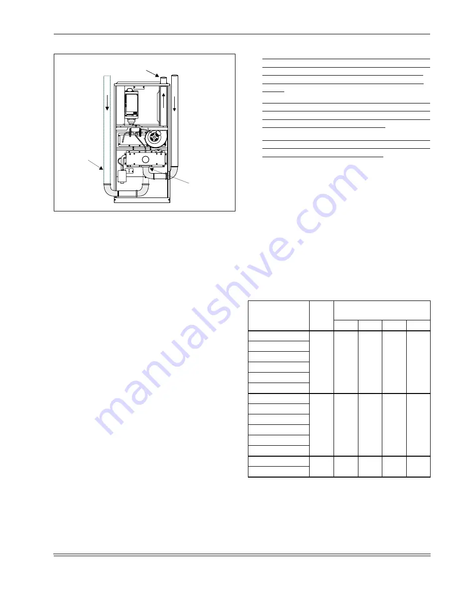
FIGURE 17 :
Air Intake and Vent Locations -
Downflow/Horizontal
OPTIONAL
LEFT SIDE
COMBUSTION
AIR PIPE
ROUTING
COMBUSTION
AIR PIPE
CONNECTS TO
COLLAR ON
BOTTOM OF
BURNER BOX
VENT PIPE PASSES
THROUGH TOP PANEL
Table 4:
INTAKE/VENT PIPING - 2 PIPE SYSTEM
Models P*UR/
FG9-UP/G9T-UP
Pipe
Size
Max. Elbows vs. One Way Vent
Length (Ft.)
*
*.
Elbow count does not include the elbows required for
the termination. See Step 4 under Combustion Air/Vent
Pipe Sizing
5 - 40
45
50
75
40 / 37 / 1000 / A
2”
6
5
4
N/A
60 / 55 / 1000 / B
80 / 75 / 1200 / B
80 / 75 / 1600 / C
100 / 95 / 1400 / C
100 / 95 / 2000 / C
40 / 37 / 1000 / A
3”
8
7
6
5
60 / 55 / 1000 / B
80 / 75 / 1200 / B
80 / 75 / 1600 / C
100 / 95 / 1400 / C
100 / 95 / 2000 / C
120 / 112 / 2000 / D
3" Only
6
5
4
N/A
140 / 130 / 2000 / D


