
035-17480-000 Rev. A (800)
8
Unitary Products Group
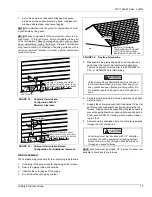
5.
Position the filter between the wire retainer and the cabi-
net wall (or floor) so it completely covers the cabinet air
opening and secure the filter in place at the front of the
cabinet by fastening the closed (looped) end of the
retainer wire under the flanged edge of the cabinet.
When properly installed the filter should fit flush with all
four sides of the cabinet wall.
NOTE: Air velocity through throw-away type filters may not
exceed 300 feet per minute. All velocities over this require the
use of high velocity filters.
Side Return - External Filter
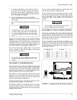
Locate and knock out the square corner locators. These indi-
cate the size of the cutout to be made in the furnace side
panel. Refer to Figure 4.
Install the side filter rack following the instructions provided
with that accessory. If a filter(s) is provided at another loca-
tion in the return air system, the ductwork may be directly
attached to the furnace side panel.
NOTE. Some accessories such as electronic air cleaners and
pleated media may require a larger side opening. Follow the
instructions supplied with that accessory for side opening
requirements.
The return duct may be attached to the furnace by S-cleat,
bend tabs or other approved methods. Be sure to seal the
duct to the furnace to prevent air leakage.
Where the return duct system is not complete, the return con-
nection must run full size to a location outside the utility room
or basement. For further details, consult Section 5.3 (Air for
Combustion and Ventilation) of the National Fuel Gas Code,
ANSI Z223.1, or CAN/CGA B149.1 or.2, Installation Code -
latest editions.
Bottom Return
Bottom return applications normally pull return air through a
base platform or return air plenum. Be sure the return plat-
form structure is suitable to support the weight of the furnace.
Refer to Figure 2 on page 7, for unit dimensions and Table 1
for unit weights. Be sure to seal the furnace to plenum con-
nection to prevent air leakage.
The bottom panel is equipped with a perforated opening for
easy removal. Tabs must be cut with sheet metal snips to
allow removing knock-out. Scribe marks are included for
forming flanges for attachment of the return air ductwork.
NOTE: If an external mounted filter rack is being used, see
the instructions provided with that accessory for proper hole
cut size.
Upflow attic installations must meet all minimum clearances
to combustibles and have floor support with required service
accessibility.
GAS PIPING
The gas supply should be a separate line and must be
installed in accordance with the National Fuel Gas Code,
ANSI Z223.1 (latest edition), or the CAN/CGA B149.1 or .2
Installation Codes (latest edition) and all applicable local and
utility requirements.
FIGURE 3 :
Filter Retainer Placement
FIGURE 4 :
Side Return Cutout Markings
RIGHT SIDE
INSTALLATION
SHOWN
CLIPS
FILTER
(PROVIDED
POSITION WIRE RETAINER
(PROVIDED) UNDER FLANGE
FURNACE
FRONT
F R O N T O F
F U R N A C E
C O R N E R
M A R K I N G S
All installations must have a filter installed.





![Roberts Gorden Combat UHD[S] 150-400 Specifications preview](http://thumbs.mh-extra.com/thumbs/roberts-gorden/combat-uhd-s-150-400/combat-uhd-s-150-400_specifications_1469644-1.webp)


