NOTE: The furnace’s control system depends on correct po-
larity of the power supply.
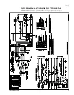
Connect the power supply as shown on the unit wiring label on
the inside of the blower compartment door and Figure 12. The
black furnace lead must be connected to the L1 (hot) wire from
the power supply. The white furnace lead must be connected
to neutral. Also, the green equipment ground wire must be
connected to the power supply ground.
Remove the screw retaining the wiring box. Route the power
wiring through the unit side panel with a conduit connector or
other proper connection. Make wiring connections as shown in
Figure 12. Replace the wiring box and screw.
An alternate wiring method is to use a field provided 2 x 4 box
and cover on the outside of the furnace. Route the furnace
leads into the box using a protective bushing where the wires
pass through the furnace panel.
NOTE: The power connection leads and wiring box on upflow
units may be relocated to the left side of the furnace.
Remove the screw and slide box and wires under manifold
bracket. Reposition on the left side of the furnace and
fasten to blower deck using hole provided.
ELECTRICAL CONTROL CONNECTIONS
Install the field-supplied thermostat. The thermostat instruc-
tions for wiring are packed with the thermostat. With the
thermostat set in the OFF position and the main electrical
source disconnected, complete the low-voltage wiring from the
thermostat to the terminal board on the low-voltage transformer.
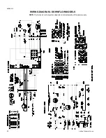
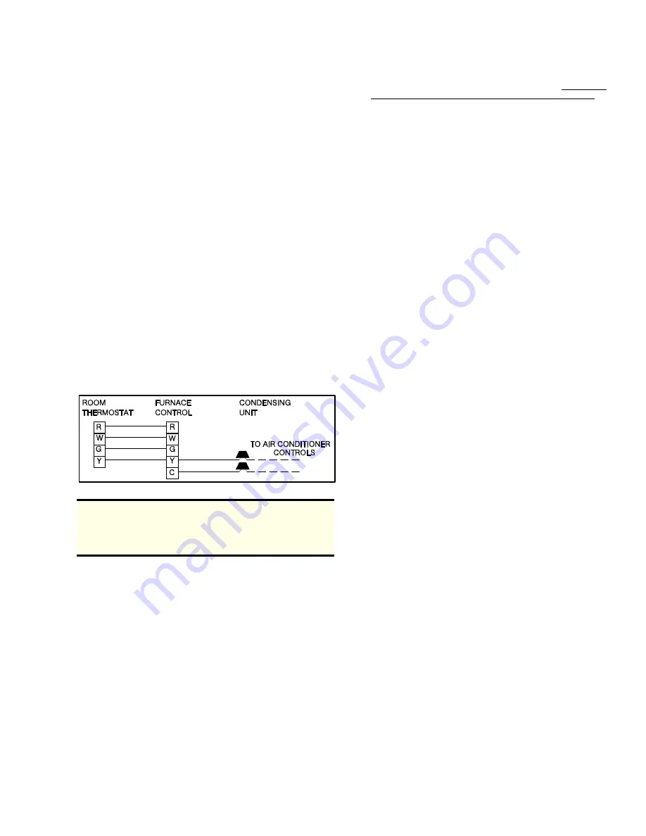
Connect Class 2 control wiring as shown in Figures 12 and 13.
NOTE: Some electronic thermostats do not have adjustable
heat anticipators. They may have other type cycle rate
adjustments. Follow the thermostat manufacturer’s in-
structions.
The 24-volt, 40 VA transformer is sized for the furnace compo-
nents only, and should not be connected to auxiliary devices
such as humidifiers, air cleaners, etc. The transformer may
provide power for an air conditioning unit contactor.
SAFETY CONTROLS
Blower Door Safety Switch
This unit is equipped with an electrical interlock switch mounted
in the blower compartment. This switch interrupts all power at the
unit when the panel covering the blower compartment is removed.
WARNING: Blower and burner must never be operated without
the blower panel in place.
Electrical supply to the unit is dependent upon the panel that
covers the blower compartment being in place and properly
positioned
CAUTION: Main power supply to the unit must still be inter-
rupted at the main power disconnect switch before any
service or repair work is to be done to the unit. Do not rely
upon the interlock switch as a main power disconnect.
Rollout Switch Controls
These controls are mounted on the burner assembly. If the
temperature in the burner compartment exceeds its set point,
the igniter control and the gas valve are de-energized. This is
a manual reset control and must be reset before operation can
continue. The operation of this control indicates a malfunction
in the combustion air blower or a blocked vent pipe connection.
Pressure Switch
This furnace is supplied with a differential pressure switch
which monitors the flow through the furnace and venting sys-
tem. This switch de-energizes the ignition control module and
the gas valve if any of the following conditions are present:
1. Blockage of internal flue gas passageways.
2. Blockage of vent piping.
3. Failure of combustion air blower/motor.
Limit Control
There is a high temperature limit control located on the furnace
vestibule panel just to the right and above the gas valve. This
is an automatic reset control and provides over temperature
protection due to reduced airflow, such as a dirty filter.
Auxiliary Limit Controls
These high temperature limit controls are located in the blower
compartment, one on each side. These are manual reset
controls and give high temperature protection when the unit is
applied in the horizontal position.
START-UP AND ADJUSTMENTS
The initial start-up of the furnace requires the following addi-
tional procedures.
1. When the gas supply is initially connected to the furnace,
the gas piping may be full of air. In order to purge this air,
it is recommended that the ground joint union be loosened
until the odor of gas is detected. When gas is detected,
immediately retighten the union and check for leaks. Allow
five minutes for any gas to dissipate before continuing with
the start-up procedure.
2. All electrical connections made in the field and in the
factory should be checked for proper tightness.
IGNITION SYSTEM CHECKOUT/ADJUSTMENT
1. Turn the gas supply ON at external valve and main gas valve.
2. Set the thermostat above room temperature to call for heat.
3. System start-up will occur as follows:
a. The venter motor will start and come up to speed.
Shortly after venter start-up, the hot surface igniter will
glow for about 31 seconds.
b. After this warm-up cycle, the ignition module will ener-
gize (open) the main gas valve for seven seconds.
NOTE: Burner ignition may not be satisfactory on first start-up
due to residual air in gas line, or until gas pressure (mani-
fold) is adjusted.
Set the heat anticipator in the room thermostat to .45
amps. Setting it lower will cause short cycles. Setting it
higher will cause the room temperature to exceed the
setpoint.
FIGURE 13 - TYPICAL HEATING AND COOLING
650.69-N3
Unitary Products Group
11


