background image

5132210-UIM-H-0916

Johnson Controls Unitary Products

13

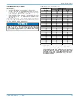
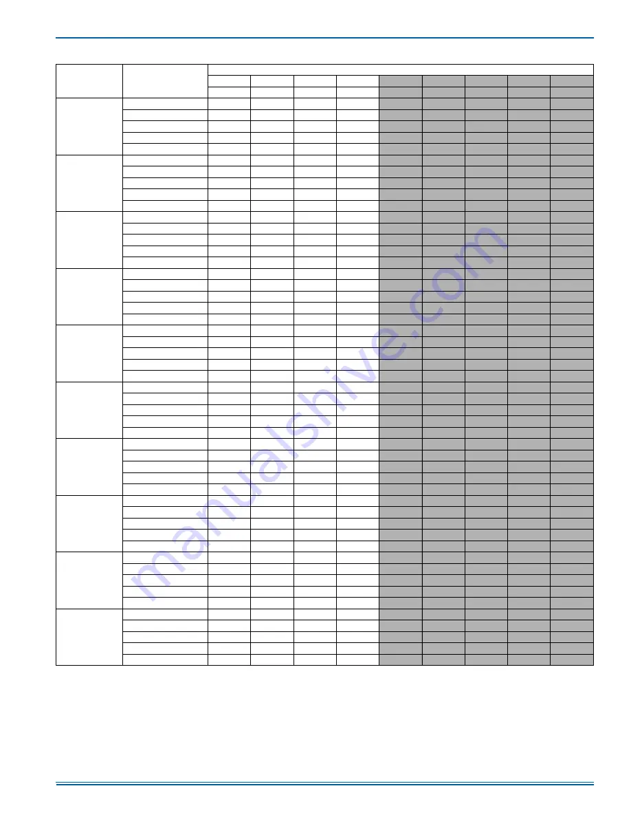
1. Airflow tested with dry coil conditions, without air filters, at 230 volts
2. Applications above 0.8" w.c. external static pressure are not recommended.
3. Brushless DC high efficiency standard ECM blower motor used for all indoor blower assemblies.
4. Minimal variations in airflow performance data results from operating at 208 volts. Data above may be used in those cases.
5. Heating applications tested at 0.50" w.c. esp, and cooling applications tested at 0.30" w.c.esp per standards.

36065

Low (1)

1231

1186

1146

1103

1069

1030

977

912

781

Low/Medium (2)

1270

1225

1189

1140

1098

1046

1008

960

866

Medium (3)

1317

1286

1245

1198

1151

1110

1064

1024

943

Medium/High (4)

1358

1317

1275

1238

1197

1148

1105

1057

961

High (5)

1517

1475

1447

1400

1357

1318

1275

1232

1146

36100

Low (1)

1340

1299

1264

1224

1182

1182

1097

1049

953

Low/Medium (2)

1409

1368

1334

1291

1253

1201

1173

1128

1038

Medium (3)

1527

1492

1470

1419

1385

1343

1299

1250

1152

Medium/High (4)

1663

1585

1594

1601

1521

1480

1440

1400

1320

High (5)

1711

1677

1643

1600

1560

1503

1466

1425

1343

42065

Low (1)

1332

1295

1263

1222

1185

1148

1110

1063

967

Low/Medium (2)

1457

1419

1376

1340

1299

1253

1215

1160

1051

Medium (3)

1451

1412

1371

1339

1296

1257

1211

1165

1072

Medium/High (4)

1568

1524

1491

1464

1425

1383

1345

1296

1200

High (5)

1711

1677

1643

1600

1560

1503

1466

1425

1343

42100

Low (1)

1455

1414

1379

1335

1294

1254

1212

1160

1056

Low/Medium (2)

1566

1532

1492

1455

1416

1372

1333

1280

1174

Medium (3)

1565

1530

1491

1458

1419

1381

1336

1290

1198

Medium/High (4)

1675

1641

1606

1578

1535

1495

1455

1412

1326

High (5)

1711

1677

1643

1600

1560

1503

1466

1425

1343

48065

Low (1)

1032

999

970

938

910

879

843

808

737

Low/Medium (2)

1272

1236

1204

1165

1129

1081

1037

968

829

Medium (3)

1611

1574

1518

1494

1439

1405

1357

1266

1083

Medium/High (4)

1892

1777

1771

1701

1639

1617

1565

1489

1336

High (5)

2131

2058

1998

1949

1892

1840

1788

1728

1608

48100

Low (1)

1598

1548

1502

1454

1410

1362

1307

1251

1139

Low/Medium (2)

1663

1612

1568

1522

1476

1422

1370

1297

1152

Medium (3)

1789

1733

1670

1650

1596

1578

1535

1483

1379

Medium/High (4)

1931

1814

1808

1736

1673

1650

1597

1519

1362

High (5)

2131

2058

1998

1949

1892

1840

1788

1728

1608

48125

Low (1)

1598

1548

1502

1454

1410

1362

1307

1251

1139

Low/Medium (2)

1766

1703

1656

1611

1566

1518

1469

1419

1319

Medium (3)

1912

1875

1805

1787

1750

1713

1672

1636

1564

Medium/High (4)

2105

2014

2006

1931

1898

1845

1793

1739

1631

High (5)

2131

2058

1998

1949

1892

1840

1788

1728

1608

60065

Low (1)

1026

999

989

950

907

907

886

862

816

Low/Medium (2)

1263

1230

1192

1165

1167

1101

1099

1071

1015

Medium (3)

1987

1933

1861

1817

1820

1715

1725

1651

1504

Medium/High (4)

2114

2050

2047

1974

1899

1889

1920

1866

1758

High (5)

2369

2308

2249

2183

2126

2088

2034

1990

1902

60100

Low (1)

1655

1612

1596

1531

1461

1462

1429

1391

1316

Low/Medium (2)

1766

1720

1667

1629

1632

1539

1537

1498

1421

Medium (3)

1987

1933

1861

1817

1820

1715

1725

1651

1504

Medium/High (4)

2114

2050

2047

1974

1899

1889

1920

1866

1758

High (5)

2369

2308

2249

2183

2126

2088

2034

1990

1902

60125

Low (1)

1973

1924

1905

1826

1743

1744

1703

1660

1574

Low/Medium (2)

2024

1983

1937

1889

1886

1843

1799

1759

1679

Medium (3)

2123

2075

2019

1970

1978

1862

1849

1804

1714

Medium/High (4)

2191

2154

2117

2075

2002

1995

2028

1974

1866

High (5)

2369

2308

2249

2183

2126

2088

2034

1990

1902

Table 13: 

Airflow Performance - Bottom Duct Application (Continued)

Model

Motor Speed

External Static Pressure (Inches WC)

0.1

0.2

0.3

0.4

0.5

0.6

0.7

0.8

1.0

SCFM

SCFM

SCFM

SCFM

SCFM

SCFM

SCFM

SCFM

SCFM

Summary of Contents for PHG4 Series

Page 1: ...or installation Only gas piping electric power and duct connections are required at the point of installation The gas fired heaters have spark ignition The refrigerant system is fully charged with R 4...

Page 2: ...mproper installation adjustment alteration service or mainte nance can cause injury or property damage Refer to this manual For assistance or additional information consult a qualified installer servi...

Page 3: ...o a unit to meet local codes they are to be installed at the dealer s and or customer s expense Size of unit for proposed installation should be based on heat loss heat gain calculation made according...

Page 4: ...are provided for this purpose WARNING Do not attach supply and return duct work to the bottom of the unit base pan as the drain pan could be compromised WARNING Excessive exposure of this furnace to...

Page 5: ...ection Distance in Direction Distance in Top3 3 Units must be installed outdoors Over hanging structure or shrubs should not obstruct condenser air discharge outlet 36 Power Entry Right Side 36 Side O...

Page 6: ...n the return air ductwork or install a Filter Frame Kit A filter rack and high velocity filters are standard on three phase units Filters must always be used and must be kept clean When filters become...

Page 7: ...rate branch circuit fed directly from the main distribution panel and properly fused Refer to Figures 7 and 8 for typical field wiring and to the appropriate unit wiring diagram for control circuit an...

Page 8: ...51 1 4 Width 35 3 4 35 3 4 45 3 4 45 3 4 45 3 4 45 3 4 Height 47 49 49 49 53 55 Operating WT lbs 394 404 449 453 498 505 532 534 551 559 564 577 581 588 Compressors Type Scroll Scroll Scroll Scroll Sc...

Page 9: ...5 The gas supply should be a separate line and installed in accor dance with all applicable safety codes After the gas connections have been completed open the main shut off valve admitting nor mal ga...

Page 10: ...leaks to check all connections A fire or explosion may result causing property damage personal injury or loss of life Table 9 High Altitude Gas Orifice Sizing ELEVATION ABOVE SEA LEVEL FEET GAS TYPE...

Page 11: ...864 780 Medium High 4 1349 1297 1265 1224 1185 1146 1107 1063 975 High 5 1487 1462 1392 1331 1318 1281 1241 1201 1121 30050 Low 1 700 657 599 554 512 461 411 365 273 Low Medium 2 906 868 825 779 735...

Page 12: ...1858 1807 1749 1710 1667 1629 1589 1546 1460 Medium 3 2054 1998 1934 1890 1843 1801 1757 1710 1616 Medium High 4 2195 2144 2098 2049 2003 1955 1883 1868 1838 High 5 2445 2388 2306 2293 2235 2178 2129...

Page 13: ...w 1 1032 999 970 938 910 879 843 808 737 Low Medium 2 1272 1236 1204 1165 1129 1081 1037 968 829 Medium 3 1611 1574 1518 1494 1439 1405 1357 1266 1083 Medium High 4 1892 1777 1771 1701 1639 1617 1565...

Page 14: ...ings are selected If the heat pump and gas heating sections are run at the same time HI LIMIT trips may occur A Y call without an O call from the indoor thermostat is primary heat pump heat A W call f...

Page 15: ...frost cycle is initiated A temperature inhibit feature prohibits defrost if the coil temperature is above 40 F A forced defrost feature puts the system into a defrost period every 6 hours and 4 minute...

Page 16: ...g 8 on the LED Post Purge The control board runs the induced draft motor for a 15 second post purge period and then de energizes the inducer If a call for heat occurs during post purge the control fin...

Page 17: ...hich automatically lights the burners 5 Remove the access panel 6 Turn the gas valve switch to the OFF position 7 Wait five 5 minutes to clear out any gas If you then smell gas STOP Follow B in the in...

Page 18: ...within the range shown on the rating plate and the data in Table 6 After the temperature rise has been determined the CFM can be calcu lated as follows Direct Drive Blower All units have direct drive...

Page 19: ...as in your particular locality Contact your gas company for this information since it varies widely from city to city Table 19 Gas Rate Cubic Feet Per Hour1 Seconds for9 One Rev Size of Test Dial 1 2...

Page 20: ...VOLTAGE 19 2 VAC PREVENTING FURTHER RELAY OUTPUTS FOR 2 SECONDS LOW VOLTAGE 16 VAC STOPPED CURRENT RELAY OUTPUTS FOR 2 SECONDS LIQUID LINE SENSOR FAILURE OPEN OR SHORTED OUTDOOR AMBIENT SENSOR FAILUR...

Page 21: ...EVENTING FURTHER RELAY OUTPUTS FOR 2 SECONDS LOW VOLTAGE 16 VAC STOPPED CURRENT RELAY OUTPUTS FOR 2 SECONDS LIQUID LINE SENSOR FAILURE OPEN OR SHORTED OUTDOOR AMBIENT SENSOR FAILURE OPEN OR SHORTED CO...

Page 22: ...Manifold sets must be at least 700 psig high side and 180 psig low side with 550 psig retard All hoses must have a service pressure rating of 800 psig Leak detectors must be designed to detect HFC re...

Page 23: ...le timer Measured voltage L1 to L2 L2 to L3 L1 to L3 Total amperes L1 L2 L3 Compressor amperes L1 L2 L3 Measured voltage R and C outdoor unit control board Electrical Connections Inspection Check all...

Page 24: ...U H Measured BTU H Clock Gas Meter Nat Gas Supply Air Dry Bulb Temp Temp Rise Return Air Dry Bulb Temp Manifold Pressure at 100 Firing Rate w c Inlet Gas Pressure w c LP Gas Conversion Kit LP Conversi...

Reviews: