5132210-UIM-H-0916
18
Johnson Controls Unitary Products
Adjust as follows:
1.
Remove the cap from the valve body. See Figure 10 for location.
2.
To decrease the gas pressure, turn the adjusting screw counter-
clockwise.
3.
To increase the gas pressure, turn the adjusting screw clockwise.
Adjustment of Temperature Rise
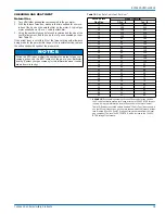
After about 20 minutes of operation, determine the furnace temperature
rise. Take readings of both the return air and the heated air in the ducts
about six feet from the furnace where they will not be affected by radi-
ant heat.
The temperature rise (or temperature difference between the return air
and the heated air from the furnace) must lie within the range shown on
the rating plate and the data in Table 6.
After the temperature rise has been determined, the CFM can be calcu-
lated as follows:
Direct Drive Blower
All units have direct drive, multi speed standard ECM blower motors.
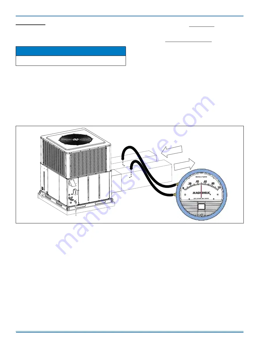
EXTERNAL STATIC PRESSURE SETUP
To measure external static pressure:
• Measure the supply air static pressure
• Record this positive number
• Measure the return air static pressure
• Record this negative number
• Treat the negative number as a positive and add the two numbers
together
• This is total system static
NOTICE
The correct manifold pressure for natural gas furnaces is 3.5 IWG.
The correct manifold pressure for propane (LP) is 10.0 IWG.
BTUH Output
1.08 x CFM
OR
CFM =
BTUH Output
Degrees F Temp Rise =
1.08 x Degrees F Temp Rise
FIGURE 11:
Measuring External Static Pressure
A0435-001
RETURN AIR
DUCT
SUPPLY AIR
DUCT


