background image

035-17311-002-A-0803

20

Unitary Products Group

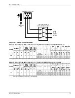
TABLE 10: ELECTRICAL DATA - DM120 (10 TON) WITHOUT POWER CONVENIENCE OUTLET

TABLE 11: ELECTRICAL DATA - DM120 (10 TON) WITH POWER CONVENIENCE OUTLET

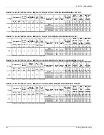
TABLE 12: ELECTRICAL DATA - DM150 (12-1/2 TON) WITHOUT POWER CONVENIENCE OUTLET

TABLE 13: ELECTRICAL DATA - DM150 (12-1/2 TON) WITH POWER CONVENIENCE OUTLET

RLA

LRA

FLA

2

3

2

3

2

3

2

3

2

3

ea.

ea.

ea.

HP

HP

HP

HP

HP

HP

HP

HP

HP

HP

None

--

--

  33.2   34.4   35.4   36.6   40   45

  45

  45

2TP04521850

  11.3

17.2

  33.2   34.4   35.4   36.6   40   45

  45

  45

2TP04522450

  15

22.8

  33.6   35.1   36.4   37.9   40   45

  45

  45

2TP04523650

  21.3

32.4

  45.6   47.1   48.3   49.8   50   50

  50

  50

2TP04525450

 33.8

51.4

 69.3  70.8   72.1   73.6   70

 80

 80

 80

*

Maximum HACR breaker of the same AMP size is applicable.

0.0

Max

Fuse

*

Size

(Amps)

Max Fuse* 

Size

w/Power

Exhaust

4.1

5.3

2.2

Actual

KW

Heater

Amps

Min. Circuit 

Ampacity

(Amps)

380

11.5

75.0

1.6

MCA

w/Power

Exhaust

(Amps)

Pwr
Exh

Motor

Pwr

Conv

Outlet

Electric Heater 

Model No.

FLA

FLA

Voltage

Compressors

OD Fan 

Motors

Supply

Blower Motor 

FLA

RLA

LRA

FLA

2

3

2

3

2

3

2

3

2

3

ea.

ea.

ea.

HP

HP

HP

HP

HP

HP

HP

HP

HP

HP

None

--

--

  39.5   40.7   41.7   42.9   50   50

  50

  50

2TP04521850

  11.3

17.2

  39.5   40.7   41.7   42.9   50   50

  50

  50

2TP04522450

  15

22.8

  41.5   43   44.2   45.7   50   50

  50

  50

2TP04523650

  21.3

32.4

  53.5   55   56.2   57.7   60   60

  60

  60

2TP04525450

 33.8

51.4

 77.2  78.7   79.9   81.4   80

 80

 80

 90

*

Actual

KW

Voltage

Compressors

OD Fan 

Motors

Supply

Blower Motor 

FLA

Max Fuse* 

Size

w/Power

Exhaust

FLA

FLA

Heater

Amps

Min. Circuit 

Ampacity

(Amps)

MCA

w/Power

Exhaust

(Amps)

Max

Fuse

*

Size

(Amps)

Pwr
Exh

Motor

Pwr

Conv

Outlet

Electric Heater 

Model No.

Maximum HACR breaker of the same AMP size is applicable.

380

11.5

75.0

1.6

4.1

5.3

2.2

6.3

RLA

LRA

FLA

3

5

3

5

3

5

3

5

3

5

ea.

ea.

ea.

HP

HP

HP

HP

HP

HP

HP

HP

HP

HP

None

--

--

  30.1   32.9   32.3   35.1   35   40

  40

  40

2TP04521850

  11.3

17.2

  30.1   32.9   32.3   35.1   35   40

  40

  40

2TP04522450

  15

22.8

  35.1   38.6   37.9   41.4   40   40

  40

  45

2TP04523650

  21.3

32.4

  47.1   50.6   49.8   53.3   50   60

  50

  60

2TP04525450

 33.8

51.4

 70.8  74.3   73.6   77.1   80

 80

 80

 80

*

Maximum HACR breaker of the same AMP size is applicable.

0.0

Max

Fuse

*

Size

(Amps)

Max Fuse* 

Size

w/Power

Exhaust

5.3

8.1

2.2

Actual

KW

Heater

Amps

Min.

Circuit

Ampacity

(Amps)

380

9.6

79.0

1.6

MCA

w/Power

Exhaust

(Amps)

Pwr
Exh

Motor

Pwr

Conv

Outlet

Electric Heater 

Model No.

FLA

FLA

Voltage

Compressors

OD Fan 

Motors

Supply
Blower

Motor FLA

RLA

LRA

FLA

3

5

3

5

3

5

3

5

3

5

ea.

ea.

ea.

HP

HP

HP

HP

HP

HP

HP

HP

HP

HP

None

--

--

  36.4   39.2   38.6   41.4   45   45

  45

  50

2TP04521850

  11.3

17.2

  36.4   39.5   38.7   42.2   45   45

  45

  50

2TP04522450

  15

22.8

  43   46.5   45.7   49.2   45   50

  50

  50

2TP04523650

  21.3

32.4

  55   58.5   57.7   61.2   60   60

  60

  70

2TP04525450

 33.8

51.4

 78.7  82.2   81.4   84.9   80

 90

 90

 90

*

Actual

KW

Voltage

Compressors

OD Fan 

Motors

Supply

Blower Motor 

FLA

Max Fuse* 

Size

w/Power

Exhaust

FLA

FLA

Heater

Amps

Min. Circuit 

Ampacity

(Amps)

MCA

w/Power

Exhaust

(Amps)

Max

Fuse

*

Size

(Amps)

Pwr
Exh

Motor

Pwr

Conv

Outlet

Electric Heater 

Model No.

Maximum HACR breaker of the same AMP size is applicable.

380

9.6

79.0

1.6

5.3

8.1

2.2

6.3

Summary of Contents for PREDATOR 150

Page 1: ...o the words NOTE CAUTION and WARNING Notes are intended to clarify or make the installation easier Cautions are given to prevent equipment damage Warnings are given to alert installer that personal injury and or equipment damage may result if installation procedure is not handled properly CONTENTS GENERAL 5 SAFETY CONSIDERATIONS 5 INSPECTION 5 REFERENCE 5 APPROVALS 5 NOMENCLATURE 6 INSTALLATION 10...

Page 2: ... AIR BALANCE 31 CHECKING AIR QUANTITY 31 METHOD ONE 31 METHOD TWO 31 SUPPLY AIR DRIVE ADJUSTMENT 32 OPERATION 33 SEQUENCE OF OPERATIONS OVERVIEW 33 COOLING SEQUENCE OF OPERATION 34 CONTINUOUS BLOWER 34 INTERMITTENT BLOWER 34 NO OUTDOOR AIR OPTIONS 34 ECONOMIZER WITH SINGLE ENTHALPY SENSOR 34 ECONOMIZER WITH DUAL ENTHALPY SENSORS 34 ECONOMIZER WITH POWER EXHAUST 34 MOTORIZED OUTDOOR AIR DAMPERS 34 ...

Page 3: ... 10 REAR DUCT DIMENSIONS 14 11 PREDATOR ROOF CURB DIMENSIONS 15 12 SUNLINE TO PREDATOR TRANSITION ROOF CURBS 15 Fig Pg 13 SIDE PANELS WITH HOLE PLUGS 16 14 RETURN DOWNFLOW PLENUM WITH PANEL 16 15 DISCHARGE PANEL IN PLACE 16 16 CONDENSATE DRAIN 16 17 ELECTRONIC THERMOSTAT FIELD WIRING 18 18 FIELD WIRING 24 VOLT THERMOSTAT 18 19 FIELD WIRING DISCONNECT 19 20 ENTHALPY SET POINT CHART 23 21 HONEYWELL ...

Page 4: ...L MOTOR DOWN SHOT BLOWER PERFORMANCE 25 19 10 TON STANDARD MOTOR DOWN SHOT BLOWER PERFORMANCE 26 Tbl Pg 20 10 TON OPTIONAL MOTOR DOWN SHOT BLOWER PERFORMANCE 26 21 12 1 2 TON STANDARD MOTOR DOWN SHOT BLOWER PERFORMANCE 27 22 12 1 2 TON OPTIONAL MOTOR DOWN SHOT BLOWER PERFORMANCE 27 23 7 1 2 TON STANDARD MOTOR SIDE SHOT BLOWER PERFORMANCE 28 24 7 1 2 TON OPTIONAL MOTOR SIDE SHOT BLOWER PERFORMANCE ...

Page 5: ...low Factory Installed 035 18286 000 Downflow Field Installed 035 18285 000 Horizontal Field Installed 035 18287 000 Motorized Outdoor Air Damper 035 18283 000 Manual Outdoor Air Damper 0 100 035 18282 000 Manual Outdoor Air Damper 0 35 035 18281 000 Electric Heater Accessory 035 17291 001 Unit Renewal Parts List 035 17288 000 All forms referenced in this instruction may be ordered from Standard Re...

Page 6: ...ector S A 4 Smoke Detector R A 5 Pwr d Conv Outlet A Standard Motor B Standard Motor Economizer Barometric Relief Downflow only C Standard Motor Economizer Power Exhaust Downflow only D Standard Motor Motorized Damper Downflow only E Standard Motor Horizontal Economizer No Barometric Relief or Power Exhaust F Standard Motor Slab Economizer Power Exhaust Downflow only G Standard Motor Slab Economiz...

Page 7: ...ap Cond Coils CP CPC Controller DFS APS Technicoat Evap Cond Coils Phase Monitor CQ CPC Controller DFS APS Technicoat Evap Cond Coils Coil Guard CR CPC Controller DFS APS Technicoat Cond Coils Phase Monitor 2 Pleated Filters CV CPC Controller DFS APS 2 Pleated Filters CX CPC Controller DFS APS Technicoat Evap Cond Coils Phase Monitor Coil Guard HA Honeywell Excel 10 Controller with Dirty Filter Sw...

Page 8: ...S APS Technicoat Evap Cond Coils Phase Monitor JQ Johnson UNT Controller DFS APS Technicoat Evap Cond Coils Coil Guard JR Johnson UNT Controller DFS APS Technicoat Evap Cond Coils Phase Monitor Coil Guard NA Novar ETC 3 Controller with Dirty Filter Switch Air Proving Switch NB Novar ETC 3 Controller DFS APS Phase Monitor NC Novar ETC 3 Controller DFS APS Coil Guard ND Novar ETC 3 Controller DFS AP...

Page 9: ...Guard TP Technicoat Evaporator Coil Phase Monitor Dirty Filter Switch TQ Technicoat Evaporator Coil Coil Guard Dirty Filter Switch TR Technicoat Evaporator Coil Phase Monitor Coil Guard Dirty Filter Switch TS Technicoat Evaporator Condenser Coils TT Technicoat Evaporator Condenser Coils Phase Monitor TU Technicoat Evaporator Condenser Coils Coil Guard TV Technicoat Evaporator Condenser Coils Dirty...

Page 10: ...e the condenser coil external protective covering prior to operation 4 Remove the toolless doorknobs and instruction packet prior to installation LIMITATIONS These units must be installed in accordance with the follow ing In U S A 1 National Electrical Code ANSI NFPA No 70 Latest Edition 2 Local building codes and 3 Local plumbing and waste water codes and 4 Other applicable local codes Refer to T...

Page 11: ...4 PREDATOR COMPONENT LOCATION Tool less door latch Side entry power and control wiring knockouts Disconnect location optional disconnect switch Filter access 2 throw away Roof curbs in eight and fourteen inch heights Roof curbs for transitioning from York Sunline footprint to the DM Series footprint are also available field installed accessory Slide out drain pan with steel 3 4 FPT connection Comp...

Page 12: ...in place when the unit is lifted The condenser coils should be protected from rig ging cable damage with plywood or other suitable material FIGURE 5 UNIT 4 POINT LOAD TABLE 3 UNIT WEIGHTS Model Shipping Weight lb Weights include largest gas heat option Operating Weight lb 54kW heater DM090 1056 1051 DM120 1121 1116 DM150 1200 1195 Econ 85 84 w PE 150 148 Elec Heat2 49 49 D A C B L E F T F R O N T ...

Page 13: ... C o n t r o l E n t r y Ø 7 8 P o w e r E n t r y Ø 2 1 2 L E F T F R O N T F o r D r a i n D i m e n s i o n s S e e D e t a i l B TABLE 6 UNIT CLEARANCES Top Units must be installed outdoors Overhanging struc ture or shrubs should not obstruct condenser air dis charge outlet 72 Right 12 Front 36 Left 36 Rear To remove the slide out drain pan a rear clearance of sixty inches is required If space...

Page 14: ... 13 16 27 1 2 18 21 24 Return Air Supply Air Bottom Condensate Entry FRONT Bottom Power Control and Convenience Outlet Wiring Entries Bottom Gas Supply Entry 12 15 16 LEFT FIGURE 10 REAR DUCT DIMENSIONS 1 8 1 4 5 5 3 2 2 8 1 4 3 1 1 1 1 6 2 3 1 3 2 1 8 1 1 6 2 8 1 4 1 8 1 4 R e t u r n A i r S u p p l y A i r P a t c h P l a t e F o r S l i d e O u t D r a i n P a n D o t P l u g s ...

Page 15: ...e necessary For side duct application remove the side duct covers and install over the bottom duct openings The panels removed from the side duct connections are designed to be reused by securing each panel to its respective downflow opening But keep in mind that the supply panel is installed with the painted surface UP facing the heat exchanger while the return panel is installed with the painted...

Page 16: ...ch filters are supplied with each unit One inch filters may be used with no modification to the filter racks Filters must always be installed ahead of evaporator coil and must be kept clean or replaced with same size and type Dirty fil ters reduce the capacity of the unit and result in frosted coils or safety shutdown All units use four 4 20 x25 x2 filters The unit should not be operated without f...

Page 17: ...as the replaced wire A disconnect must be utilized for these units Factory installed disconnects are available If installing a disconnect field supplied or York International supplied accessory refer to Figure 4 for the recommended mounting location NOTE Since not all local codes allow the mounting of a dis connect on the unit please confirm compliance with local code before mounting a disconnect ...

Page 18: ... 1 0 0 2 4 i n c l u d e s s u b b a s e 2 T e r m i n a l s A 1 a n d A 2 p r o v i d e a r e l a y o u t p u t t o c l o s e t h e o u t d o o r e c o n o m i z e r d a m p e r s w h e n t h e t h e r m o s t a t s w i t c h e s t o t h e s e t b a c k p o s i t i o n 2 4 V o l t T r a n s f o r m e r 2 T O R E M O T E S E N S O R 2 E T 0 4 7 0 1 3 2 4 I F U S E D FIGURE 18 FIELD WIRING 24 VOLT ...

Page 19: ...MP size is applicable 0 0 Max Fuse Size Amps Max Fuse Size w Power Exhaust 3 1 4 1 2 2 Actual KW Heater Amps Min Circuit Ampacity Amps 380 7 1 54 0 0 8 MCA w Power Exhaust Amps Pwr Exh Motor Pwr Conv Outlet Electric Heater Model No FLA FLA Voltage Compressors OD Fan Motors Supply Blower Motor FLA RLA LRA FLA 1 5 2 1 5 2 1 5 2 1 5 2 1 5 2 ea ea ea HP HP HP HP HP HP HP HP HP HP None 27 28 29 2 30 2 ...

Page 20: ...FLA Max Fuse Size w Power Exhaust FLA FLA Heater Amps Min Circuit Ampacity Amps MCA w Power Exhaust Amps Max Fuse Size Amps Pwr Exh Motor Pwr Conv Outlet Electric Heater Model No Maximum HACR breaker of the same AMP size is applicable 380 11 5 75 0 1 6 4 1 5 3 2 2 6 3 RLA LRA FLA 3 5 3 5 3 5 3 5 3 5 ea ea ea HP HP HP HP HP HP HP HP HP HP None 30 1 32 9 32 3 35 1 35 40 40 40 2TP04521850 11 3 17 2 3...

Page 21: ...a field installed accessory If factory installed refer to the instructions included with the outdoor air hood to com plete the assembly Field installed Motorized Outdoor Damper accessories include complete instructions for instal lation TABLE 14 PHYSICAL DATA Component Models 090 120 150 Evaporator Blower Blower Centrifugal Dia X Wd in 15 x 15 15 x 15 15 x 15 Motor Standard HP 1 1 2 2 3 Motor Opti...

Page 22: ...desired minimum damper position has been attained ENTHALPY SET POINT ADJUSTMENT The enthalpy set point may now be set by selecting the desired set point shown in the Enthalpy Set Point Adjustment Figure 20 Adjust as follows For a single enthalpy operation carefully turn the set point adjusting screw found on the damper control mod ule to the A B C or D setting corresponding to the lettered curve o...

Page 23: ...D C C B B A A CONTROL CURVE CONTROL POINT APPROX 0 F 0 C AT 50 RH A D C B 63 17 73 23 70 21 67 19 FIGURE 21 HONEYWELL ECONOMIZER CONTROL W7212 N1 N P1 P EXH Set EXH Min Pos IAQ Max IAQ IAQ Min Free Cool T T1 AQ1 AQ SO SO SR SR A B C D TR TR1 24 Vac HOT 24 Vac COM EF EF1 2 3 4 5 1 Exhaust Air Adjustment Screw Exhaust Air LED Damper Min Position Screw Indoor Air Quality Max Adjustment Screw Indoor A...

Page 24: ...oper rotation to oper ate correctly Units are properly phased at the fac tory Do not change the internal wiring to make the blower condenser fans or compressor rotate cor rectly TABLE 16 SUPPLY AIR LIMITATIONS Unit Size Minimum Maximum 090 2250 3750 120 3000 5000 150 3750 6250 FIGURE 22 BELT ADJUSTMENT Procedure for adjusting belt tension 1 Loosen six nuts top and bottom A 2 Adjust by turning B 3 ...

Page 25: ...variable pitch motor sheave where 0 Turns Open is fully closed W Watts TABLE 18 7 1 2 TON OPTIONAL MOTOR DOWN SHOT BLOWER PERFORMANCE ESP TURNS OPEN 0 1 2 3 4 5 CFM W BHP CFM W BHP CFM W BHP CFM W BHP CFM W BHP CFM W BHP 0 2 3992 1904 2 04 3798 1679 1 80 0 4 3930 2017 2 16 3734 1786 1 92 3486 1552 1 66 0 6 3947 2176 2 33 3670 1895 2 03 3394 1641 1 76 3084 1401 1 50 0 8 4138 2384 2 56 3623 2009 2 1...

Page 26: ...s fully closed W Watts TABLE 20 10 TON OPTIONAL MOTOR DOWN SHOT BLOWER PERFORMANCE ESP TURNS OPEN 0 1 2 3 4 5 CFM W BHP CFM W BHP CFM W BHP CFM W BHP CFM W BHP CFM W BHP 0 4 4965 3485 3 74 4875 3150 3 38 4613 2739 2 94 4322 2374 2 55 4156 2106 2 26 3907 1860 1 99 0 6 4876 3416 3 66 4651 2997 3 21 4359 2582 2 77 4038 2220 2 38 3860 1966 2 11 3590 1724 1 85 0 8 4713 3291 3 53 4387 2823 3 03 4077 241...

Page 27: ... ESP TURNS OPEN 0 1 2 3 4 5 CFM W BHP CFM W BHP CFM W BHP CFM W BHP CFM W BHP CFM W BHP 0 4 5994 5400 5 79 5565 4369 4 69 5488 4169 4 47 5264 3599 3 86 4990 3085 3 31 4738 2812 3 02 0 6 5824 5216 5 59 5368 4186 4 49 5289 3991 4 28 5049 3437 3 69 4763 2937 3 15 4491 2655 2 85 0 8 5641 5022 5 39 5170 4012 4 30 5076 3807 4 08 4822 3272 3 51 4528 2790 2 99 4235 2497 2 68 1 0 5444 4819 5 17 4971 3846 4...

Page 28: ... refers to the setting of the variable pitch motor sheave where 0 Turns Open is fully closed W Watts TABLE 24 7 1 2 TON OPTIONAL MOTOR SIDE SHOT BLOWER PERFORMANCE ESP TURNS OPEN 0 1 2 3 4 5 CFM W BHP CFM W BHP CFM W BHP CFM W BHP CFM W BHP CFM W BHP 0 4 3910 1726 1 85 0 6 3857 1842 1 98 3597 1430 1 53 0 8 3804 1957 2 10 3503 1689 1 81 3172 1430 1 53 1 0 3774 2088 2 24 3406 1778 1 91 3032 1497 1 6...

Page 29: ...s fully closed W Watts TABLE 26 10 TON OPTIONAL MOTOR DOWN SHOT BLOWER PERFORMANCE ESP TURNS OPEN 0 1 2 3 4 5 CFM W BHP CFM W BHP CFM W BHP CFM W BHP CFM W BHP CFM W BHP 0 4 4965 3485 3 74 4875 3150 3 38 4613 2739 2 94 4322 2374 2 55 4156 2106 2 26 3907 1860 1 99 0 6 4876 3416 3 66 4651 2997 3 21 4359 2582 2 77 4038 2220 2 38 3860 1966 2 11 3590 1724 1 85 0 8 4713 3291 3 53 4387 2823 3 03 4077 241...

Page 30: ...riable pitch motor sheave where 0 Turns Open is fully closed W Watts TABLE 28 12 1 2 TON OPTIONAL MOTOR SIDE SHOT BLOWER PERFORMANCE ESP TURNS OPEN 0 1 2 3 4 5 CFM W BHP CFM W BHP CFM W BHP CFM W BHP CFM W BHP CFM W BHP 0 4 6447 5315 5 70 6207 4760 5 1046 5966 4205 4 51 5717 3716 3 98 5470 3307 3 55 0 6 6110 4917 5 27 5965 4464 4 79 5740 4023 4 31 5430 3501 3 75 5126 3054 3 28 0 8 5772 4519 4 85 5...

Page 31: ... in the supply air duct as close to the outlet of the unit as possible 2 Using the whole drilled in step 1 insert eight inches of 1 4 inch metal tubing into the airflow of the return and supply air ducts of the unit NOTE The tubes must be inserted and held in position per pendicular to the airflow so that velocity pressure will not affect the static pressure readings 3 Use an Inclined Manometer or...

Page 32: ...d DD for the new motor sheave 4 000 CFM 3 800 CFM Use Table 31 to locate the DD nearest to 4 21 in Close the sheave to 1 turn open New BHP 3 Speed increase BHP at 3 800 CFM 3 Speed increase Original BHP New BHP New motor Amps 3 Speed increase Amps at 3 800 CFM 3 Speed increase Original Amps New Amps FIGURE 23 DRY COIL DELTA P Before making any blower speed changes review the installation for any i...

Page 33: ... 3900 0 23 0 04 0 19 0 20 0 23 0 24 0 28 4100 0 25 0 04 0 21 0 22 0 25 0 26 0 31 4300 0 28 0 05 0 23 0 24 0 28 0 29 0 34 4500 0 30 0 05 0 25 0 26 0 30 0 31 0 37 4700 0 33 0 05 0 28 0 29 0 33 0 34 0 40 4900 0 36 0 05 0 30 0 31 0 35 0 37 0 43 5100 0 39 0 06 0 33 0 34 0 38 0 40 0 46 5300 0 42 0 06 0 35 0 37 0 41 0 43 0 49 5500 0 45 0 06 0 38 0 40 0 44 0 46 0 53 5700 0 48 0 06 0 41 0 43 0 47 0 49 0 56...

Page 34: ...rol circuit from R to G and Y1 is com pleted The UCB energizes the blower motor if the fan switch on the room thermostat is set in the AUTO position and drives the economizer dampers from fully closed to their min imum position If the enthalpy of the outdoor air is below the set point of the enthalpy controller previously determined Y1 energizes the economizer The dampers will modulate to maintain...

Page 35: ...eration the UCB will lock out the associated compressor and flash a code 37 If the other compressor is inactive the condenser fans will be de energized LOW AMBIENT COOLING To determine when to operate in low ambient mode the UCB has a pair of terminals connected to a temperature activated switch set at 45ºF When the low ambient switch is closed and the thermostat is calling for cooling the UCB wil...

Page 36: ...ll times If the temperature limit opens three times within one hour it will lock on the indoor blower motor and a flash code is initi ated See Table 37 SAFETY CONTROLS The UCB monitors the temperature limit switch of electric heat units The control circuit includes the following safety controls LIMIT SWITCH LS This control is located inside the heater compartment and is set to open at the temperat...

Page 37: ... will energize after the built in time delay five minutes 4 The second stage of the thermostat will energize second stage compressor if needed POST START CHECK LIST 1 Verify proper system pressures for both circuits 2 Measure the temperature drop across the evaporator coil CHARGING THE UNIT These units should be charged using the superheat method Super heat charging data is shown in Tables 34 thru...

Page 38: ...8 9 105 5 7 8 1 10 6 13 1 15 5 110 5 5 7 7 10 0 12 2 115 6 9 8 9 TABLE 36 12 5 TON STANDARD EFFICIENCY SUPERHEAT CHARGING Outdoor Temp F Superheat at Compressor Suction F Airflow 5000 CFM Indoor WB Temp F 55 57 59 61 63 65 67 69 71 73 75 65 33 6 34 2 34 7 35 3 35 9 36 4 37 0 37 3 37 5 37 8 38 0 70 29 6 30 4 31 1 31 9 32 7 33 4 34 2 34 7 35 3 35 8 36 3 75 25 6 26 6 27 5 28 5 29 5 30 5 31 4 32 2 33 ...

Page 39: ...usion a 1 flash flash code is not used Current alarms are flashed on the UCB LED The alarm his tory can be checked by pressing and releasing the ALARMS button on the UCB The UCB will cycle through the last five 5 alarms most recent to oldest separating each alarm flash code by approximately 2 seconds In some cases it may be necessary to zero the ASCD for the compressors in order to perform trouble...

Page 40: ...lashes Compressors Locked Out Because The Economizer Is Using Free Cooling 12 Flashes Fan Overload Switch Trip Not Applicable On This Unit 13 Flashes Compressor Held Off Due To Low Voltage 14 Flashes EEPROM Storage Failure Control Failure OFF No Power or Control Failure These flash codes do not represent alarms FIGURE 24 BASIC TROUBLESHOOTING FLOWCHART Monitor Monitored Systems Problem Call for Co...

Page 41: ...If the thermostat and UCB are properly wired replace the UCB On calls for cooling the supply air blower motor is operating but compressor 1 is not the room thermostat fan switch is in the AUTO position 1 If installed check the position of the economizer blades If the blades are open the economizer is providing free cooling and the compressors will not immediately oper ate If both stages of cooling...

Page 42: ...for this programming 15 If none of the above corrected the error test the integrity of the UCB Disconnect the C1 terminal wire and jumper it to the Y1 terminal DO NOT jump the Y1 to C1 termi nals If the compressor engages the UCB has faulted 16 If none of the above correct the error replace the UCB On calls for the second stage of cooling the supply air blower motor and compressor 1 are operating ...

Page 43: ...ill does not operate replace the compressor 6 If 24 volts is not present at M1 check for 24 volts at the UCB terminal C1 If 24 volts is present check for loose wiring between C1 and the compressor contactor 7 If 24 volts is not present at the C1 terminal check for 24 volts from the room thermostat at the UCB Y1 terminal If 24 volts are not present at the UCB Y1 terminal the UCB may have faulted Ch...

Page 44: ...ntrol may have faulted and is not returning the 24 volts to the Y1 ECON terminal even though the economizer is not providing free cooling To test the economizer control disconnect the Mate N Locks and jumper between the WHITE and YELLOW wires of the UCB s Mate N Lock plug 13 The UCB can be programmed to lock out compressor operation during free cooling and in low ambient condi tions These options ...

Reviews: