035-19671-002 Rev. A (0704)
Unitary Products Group
7
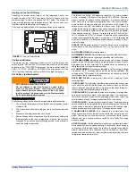
Heating Indoor Fan Off Delay
Changing the blower delay jumper on the Integrated Control can
change the indoor fan “OFF” time delay. Refer to Figure 8 for the
jumper settings to obtain the desired fan OFF delay. The blower off
delay must be long enough to adequately cool the furnace, but not so
long that cold air is blown into the living space.
The blower on delay is fixed at 30 seconds and cannot be adjusted.
Continuous Blower:
The blower will run continuously whenever the wall thermostat fan
switch is in the "ON" position. The furnace blower will run at the speed
selected on the "FAN SPEED" jumpers on the main control board (HI
COOL, LO COOL, HI HEAT or LO HEAT). When the jumper is in the
"VS G" position, the blower will run at 50% of the high cool speed.
Hot Surface Ignition System
TROUBLESHOOTING
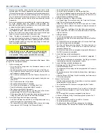
The following visual checks should be made before troubleshooting:
1.
Check to see that the power to the furnace and the ignition control
module is ON.
2.
The manual shut-off valves in the gas line to the furnace must be
open.
3.
Make sure all wiring connections are secure.
4.
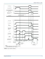
Review the sequence of operation. Start the system by setting the
thermostat above the room temperature. Observe the system’s
response. Then use the troubleshooting section in this manual to
check the system’s operation.
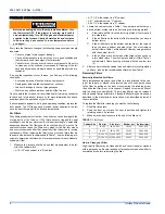
FURNACE DIAGNOSTICS
The furnace has built-in, self-diagnostic capability. If a system problem
occurs, a blinking LED shows a fault code. The LED can flash red,
green or amber to indicate various conditions. It is located behind a
clear view port in the blower compartment door. The control continu-
ously monitors its own operation and the operation of the system. If a
failure occurs, the LED will indicate the failure code. If the failure is
internal to the control, the light will stay on continuously. In this case, the
entire control should be replaced, as the control is not field repairable.
Flash sequence codes 1 through 11 are as follows: LED will turn "on"
for 1/4 second and "off" for 1/4 second. This pattern will be repeated the
number of times equal to the code. For example, six "on" flashes equals
a number 6 fault code. All flash code sequences are broken by a 2 sec-
ond "off" period.
STEADY OFF
No power to board. Check the 24 vac control circuit fuse
on the board or the circuit breakers on the 115 vac power to the fur-
nace.
SLOW GREEN FLASH:
Normal operation.
SLOW AMBER FLASH:
Normal first stage operation with call for heat.
AMBER PULSE
Normal second stage operation with call for heat.
3 FLASHES AMBER
Indicates a second stage call for heat (Voltage
present on the W2 terminal) with no single stage call for heat (No volt-
age present on the W1 terminal). This condition may be caused by a
faulty thermostat or faulty thermostat wiring.
4 FLASHES AMBER
This condition indicates a call for cooling (Voltage
Present on the "Y" terminal) with no call for indoor fan operation (No
voltage on the "G" terminal). This condition may be caused by a faulty
thermostat or faulty thermostat wiring.
RAPID RED FLASH:
Twinning error, incorrect 24V phasing. Check
twinning wiring.
1 RED FLASH:
This indicates that flame was sensed when there was
not a call for heat. With this fault code the control will turn on both the
inducer motor and supply air blower. A gas valve that leaks through or
is slow closing would typically cause this fault.
2 RED FLASHES:
This indicates that the normally open 1st stage pres-
sure switch contacts are stuck in the closed position. The control con-
firms these contacts are open at the beginning of each heat cycle. This
would indicate a faulty 1st stage pressure switch or mis-wiring.
3 RED FLASHES:
This indicates the normally open 1st stage pressure
switch contact did not close after the inducer was energized. This could
be caused by a number of problems: faulty inducer, blocked vent pipe,
broken pressure switch hose or faulty 1st stage pressure switch.
3 DOUBLE RED FLASHES:
This indicates the normally open 2nd
stage pressure switch contact did not close after the inducer was ener-
gized. This could be caused by a number of problems: faulty inducer,
blocked vent pipe, broken pressure switch hose or faulty 2nd stage
pressure switch.
4 RED FLASHES:
This indicates that a primary or auxiliary limit switch
has opened its normally closed contacts 5 consecutive times during a
call for heat. With this fault code the control will operate the supply air
blower and inducer. This condition may be caused by: dirty filter,
improperly sized duct system, incorrect blower speed setting, incorrect
firing rate or faulty blower motor.
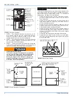
FIGURE 7:
Furnace Control Board
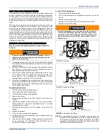
HOT SURFACE IGNITION SYSTEM
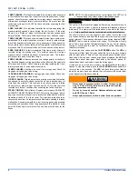
Do not attempt to light this furnace by hand (with a
match or any other means). There may be a potential
shock hazard from the components of the hot surface
ignition system. The furnace can only be lit automatically
by its hot surface ignition system.
Y1
Y2
Y
W1
W
W2
R
G
C


