0171-971
3
the torques indicated in the
Instruction Manual.
Make sure that the O-ring pos. 156F has
been fitted in the balance piston before the piston is mounted.
S
Mount the rotating part of the shaft seal pos. 160A and tighten it by means of the
pointed screws pos. 160E. Make sure that the O-ring has been mounted in the rotating
part.
S
Mount the slide ring pos. 156C which is tightened by means of the four countersunk
screws pos. 156I. Make sure that the O-ring pos. 156G has been mounted.
Before mounting the shaft seal cover pos. 156A on the compressor block, carry out the fol-
lowing:
S
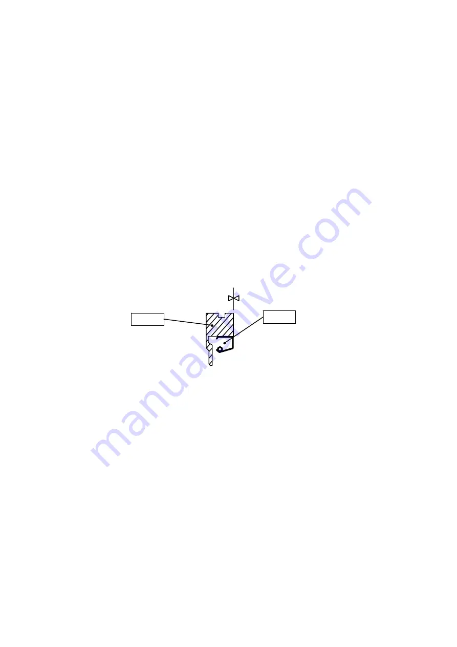
Press the sealing ring pos. 156D into the retaining ring pos. 156E. It must be turned
as shown in the drawing fig. 2 and must only be pressed so far into the retaining ring
that the two surfaces are
flush
with each other as illustrated in fig. 2.
Fig. 2
156D
Plane
156E
S
Fit the retaining ring pos. 156E in the shaft seal cover pos. 156A. Turn it so that the
two screws pos. 156K can be mounted and tightened. Make sure that the O-ring pos.
156H has been mounted on the retaining ring.
Note, moreover, that there are two types of shaft seal covers and retaining rings for male
and female compressor. The many bored holes in the retaining ring must be placed
above
the centre line of the compressor shaft when the shaft seal cover has been fitted
on the compressor.
S
Mount the cast iron seat pos. 160B and the O-ring pos. 160D in the shaft seal cover.
Make sure that the pin pos. 161 catches the slot in the cast iron seat.
S
Mount the O-ring pos. 164.
S
Move the shaft seal cover carefully over the compressor shaft until it touches the rotating
part of the shaft seal. Before the screws pos. 167 are tightened, there must be a gap of
3-4 mm between the two flanges as illustrated in fig. 4.1 in the
Instruction Manual.


