background image

SOLUTION™ XT

INDOOR AND OUTDOOR UNITS

SOLUTION™ 

AIR HANDLING UNITS

INSTALLATION AND ASSEMBLY

Supersedes: 102.20-N1 (615)

Form 102.20-N1 (716)

Issue Date: 

July 6, 2016

LD09624

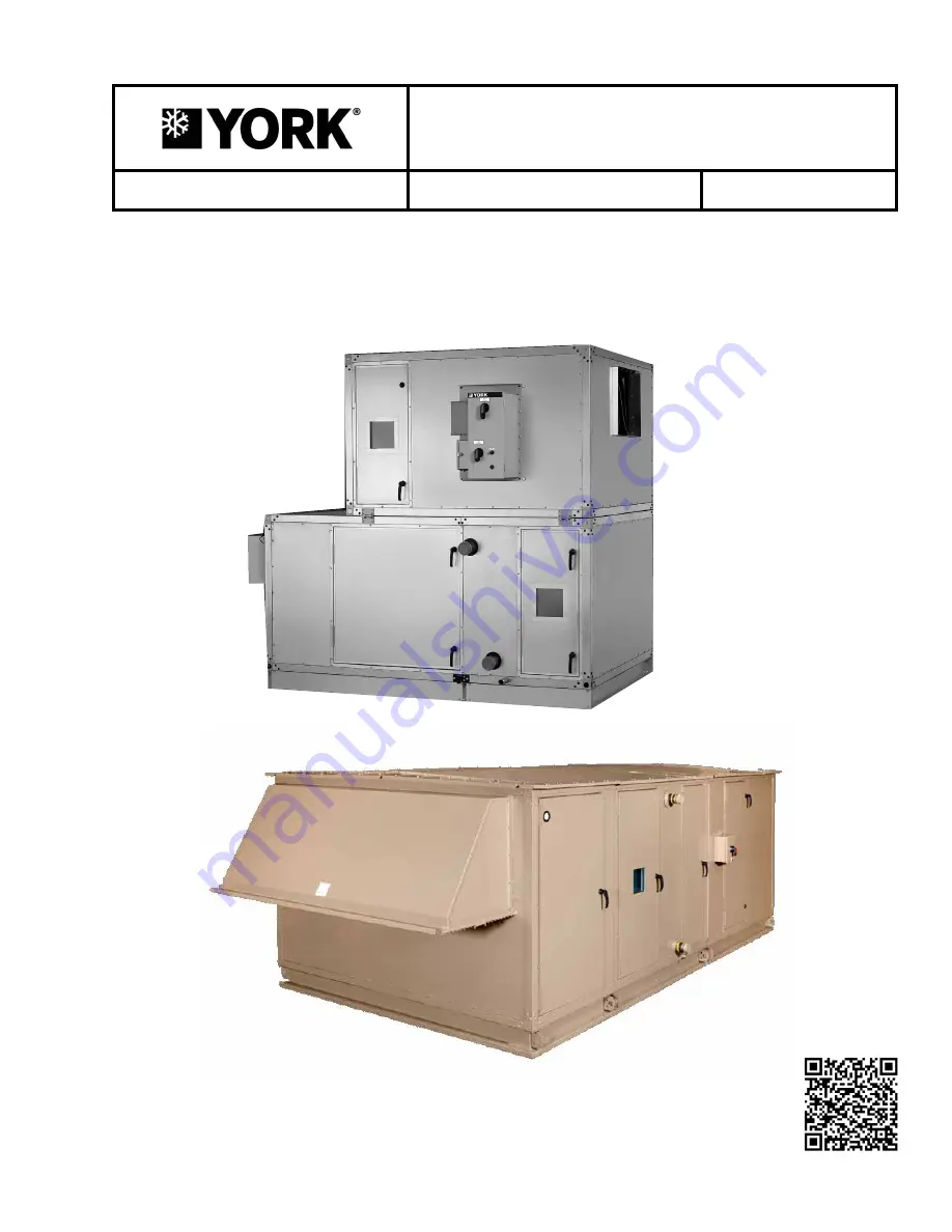
OUTDOOR AHU (XTO)

INDOOR AHU (XTI)

LD17323

Summary of Contents for SOLUTION XTI Series

Page 1: ...LUTION XT INDOOR AND OUTDOOR UNITS SOLUTION AIR HANDLING UNITS INSTALLATION AND ASSEMBLY Supersedes 102 20 N1 615 Form 102 20 N1 716 Issue Date July 6 2016 LD09624 OUTDOOR AHU XTO INDOOR AHU XTI LD173...

Page 2: ...this document and any referenced materials This in dividual shall also be familiar with and comply with all applicable industry and governmental standards and regulations pertaining to the task in que...

Page 3: ...es no commitment to update or provide current information automatically to the manual or product owner Updated manuals if applicable can be obtained by contacting the nearest Johnson Controls Service...

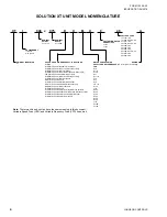
Page 4: ...an with Service Disconnect only M SWSI PL Fan with Motor Starter N SWSI PL Fan with VFD P SWSI PL Fan Direct Drive without Motor Controller Q SWSI PL Fan Direct Drive with Service Disconnect Only R SW...

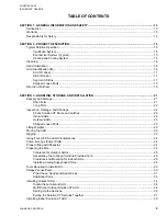
Page 5: ...Inspection Damage and Shortage 22 Check Solution XT Doors and Latches 23 Indoor AHUs 23 Outdoor AHUs 23 Shipped Loose Parts 23 Lifting Weights 23 Moving the AHU 23 Rigging 23 Using Fork Lift in Specia...

Page 6: ...hase 57 Tools and Materials 57 Preparing Pipe Chase for Installation 57 Apply Gaskets 57 Attach Pipe Chase 58 Seal Pipe Chase to Solution XT AHU 59 Install Cover Angles 59 Install Base Rail Covers If...

Page 7: ...Connections 91 Duct Connection Guidelines 91 Flanged Duct or Sleeves 91 Raw or Straight Edge Duct or Sleeves 91 Sound and Vibration Transmission 92 Installing Top Discharge Outdoor AHU Duct 92 Install...

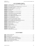
Page 8: ...9 000 30 FIGURE 23 Bottom Raceway Shipping Split Fastener Pack P N 386 03418 000 31 FIGURE 24 Base Rail Shipping Split Fastener Pack P N 386 03417 000 31 FIGURE 25 Top Raceway Bracket Assembled P N 38...

Page 9: ...N 386 03419 000 44 FIGURE 67 Apply Gaskets to Top Panel on Bottom Tier 44 FIGURE 68 Guide Brackets Together 44 FIGURE 69 Solution XT Lights Tier Transition Drawing 45 FIGURE 70 Assembling the End Chan...

Page 10: ...Chase Enclosure 73 FIGURE 115 Factory Coil Connections 74 FIGURE 116 Staggered Coil Angled Wall 74 FIGURE 117 Split Coil Opposite Side Connections 74 FIGURE 118 Chilled Water Coil Connections Example...

Page 11: ...talled Latch Pin P N 026 35788 702 98 FIGURE 149 Fully Installed Filter 98 FIGURE 150 Correctly Installed Latch Pin P N 026 35788 604 98 FIGURE 151 Place the End of the Latch Over the Filter Frame 99...

Page 12: ...Damage and Shortage 22 Receiver s Responsibility 23 Shipped Loose Parts 23 Installing Ceiling Suspended AHUs 29 Installing Damper Actuator 48 Installing Multi Zone MZ Dampers 51 Installing Field Suppl...

Page 13: ...s detailed in the manual WARRANTY Johnson Controls warrants AHUs in accordance with the Limited Warranty Engineered Systems Equipment procedure Refer to the Standard Limited Warranty Engineered System...

Page 14: ...JOHNSON CONTROLS 14 FORM 102 20 N1 ISSUE DATE 7 06 2016 SECTION 1 GENERAL INFORMATION AND SAFETY THIS PAGE INTENTIONALLY LEFT BLANK...

Page 15: ...cool and dry enough to satisfy the internal cooling demand The outdoor and the return air dampers are operated by individual ac tuators As the outdoor air dampers are opened by the damper actuator th...

Page 16: ...ts are located and described as left or right hand The proper orientation to describe the proper hand is when airflow is at your back as shown in Figure 2 on page 16 AHU IDENTIFICATION ID Indoor and o...

Page 17: ...i piece AHU is marked with a skid ID label which indicates its order of assembly in the direction of airflow as shown in Figure 4 on page 17 Segment ID Box The segment ID box indicates the skids and s...

Page 18: ...MZ MULTI ZONE HEAT SEGMENTS IC INTEGRAL FACE AND BYPASS COIL IG INDIRECT GAS FIRED FURNACE EH ELECTRIC HEATER ENERGY RECOVERY ER HEAT WHEEL HW HEAT WHEEL FILTER SEGMENTS FF FLAT FILTER 2 or 4 in AF A...

Page 19: ...he loose component is used in only one seg ment on a skid the segment ID i e MB will be bold as shown in Figure 6 on page 19 Figure 7 on page 19 shows a hood label for an outdoor AHU Figure 8 on page...

Page 20: ...JOHNSON CONTROLS 20 FORM 102 20 N1 ISSUE DATE 7 06 2016 SECTION 2 PRODUCT DESCRIPTION THIS PAGE INTENTIONALLY LEFT BLANK...

Page 21: ...to cover and protect the AHUs from Dust Rain and snow Rodents Construction vehicles and personnel Condensation Ventilation required Protect all parts and porous materials from rain and other sources...

Page 22: ...ail car when received be fore unloading for any visible signs of damage Report any damage or signs of possible damage to the trans portation company immediately for its inspection After inspecting the...

Page 23: ...prevent damage from job site dirt and various weather condi tions If the Solution XT AHU is covered with plastic cut the wrap in the outline of the door s and proceed to access the Solution XT AHU usi...

Page 24: ...components and should be handled in an upright position Care must be exercised to avoid twisting the equipment structure Prevent unnecessary jarring or rough handling Proper rigging and handling of th...

Page 25: ...ly into the se lected location use the following instructions Allow sufficient space around theAHU to remove the access panels and various parts Provide a minimum clearance equal to the width of the A...

Page 26: ...ether to form rectangular perimeter as shown leaving bolts loose After the curb is set in place ensure proper consideration has been given to the air duct openings through the roof 4 The curb installa...

Page 27: ...curb Mtg will be field located C Pipe chase length muinus 0 875 in D Total unit width from YORKworks minus 0 875 in WALL PANEL STANDARD RACEWAY CURB GASKET CURB REST 2 in X 4 in NAILER NOMINAL ROOF C...

Page 28: ...of the AHU plus 6 in must be pro vided on one side of the AHU to remove the coil or fan assembly Concrete pads may not be as flat as they should be Shimming and or grouting may be necessary Whether un...

Page 29: ...Positioned Perpendicular to Airflow The AHUs must be supported at a minimum at the following locations Both ends At each shipping split if applicable Upstream and downstream of each cooling coil segme...

Page 30: ...ASSEMBLE SHIPPING SPLITS LD09613 When the AHU is shipped in skids re place the curb gasket with the the caulk provided by the contractor because gas kets on curbs can pose a problem when sliding skids...

Page 31: ...NG SPLIT FASTENER PACK P N 386 03417 000 LD11032a 1 2 x 5 1 2 in Hex Cap Screw 2 0 56 in ID x 1 38 in OD Flat Washer 2 Lock Washer 2 1 2 in Hex Nut Raceway Lifting Lugs Assembled Figure 25 TOP RACEWAY...

Page 32: ...IN X 3 4 IN X 40 FT P N 013E 03327 010 LD116509 Figure 31 POLYURETHANECAULK P N 021 19568 000 GREY P N 013 03317 040 CHAMPAGNE FOR PIPE CHASE ONLY LD116505 Never use silicone caulk sealant in or on a...

Page 33: ...hese instruc tions Figure 35 DAMPER SHAFT EXTENSION KIT P N 026 33715 002 LD116504 LD16514 Figure 36 CORNER CONNECTOR HOLE PLUG P N 021 19568 000 8 Figure 37 TOUCH UP SPRAY 12 OZ P N 013 03322 000 LD1...

Page 34: ...tate and local codes Multi Piece Outdoor Solution XT AHU Before placing the AHU on the curb do the following 1 If applicable remove the metal bracket attached to the cross channel and wood shipping bl...

Page 35: ...T RACEWAY WITH LUG AND CURB REST BOTTOM SPLIT RACEWAY BASERAIL WITH LUG BOTTOM SPLIT RACEWAY BASERAIL WITH LUG AND CURB REST CURB REST Figure 42 SHIPPING SPLIT EXAMPLES USING STRUCTURAL STEEL BASERAIL...

Page 36: ...NEOPRENE GASKET GASKET SQUARE RACEWAY SPLIT CAULK Setting Up the Sections Use the following instructions to set up the sections 1 Place the first section on the curb Position it so that the overhangin...

Page 37: ...t section as shown in Figure 48 on page 37 Figure 48 COME A LONG ATTACHED TO A SECTION LD13775 COME A LONG Make sure the chain does not apply pres sure to the drain connection Improper positioning of...

Page 38: ...00 5 Fasten the top raceway bracket with the 1 2 in x 5 1 2 in bolts provided in fastener packet P N 386 03418 000 6 Apply a 1 4 in bead of caulking to exterior of the seam on the roof and both sides...

Page 39: ...ientation of each section 4 Remove the cross brace s shipping supports from each section s shipping split 5 Remove the plastic shipping covers and supports 6 Apply neoprene gasket P N 028 15954 010 to...

Page 40: ...line up properly 5 Attach the sections as follows a Make sure assembly surface is clean and lev el to allow the sections to slide freely If the surface is irregular use as many metal shims under sect...

Page 41: ...ing lugs within the shipping split shown in Fig ure 57 on page 41 Keep the bolts and nuts Figure 57 REMOVE LIFTING LUGS IN EXPANDED CABINET LD14265 LIFTING LUG BASE CHANNEL WELDED CHANNEL FILLER 4 Pla...

Page 42: ...rift pins through the holes in the lifting lugs on opposite sections simul taneously d If there is any difficulty aligning the sections due to racking of one section or the other use a come a long dia...

Page 43: ...each additional section 15 For AHUs or sections without base rails install the corner connector hole plugs P N 021 19568 000 as shown in Figure 64 on page 43 on the bottom raceway corners Figure 64 S...

Page 44: ...f the gasket applied in Step 5 but include the raceways Steps 5 and 6 are necessary because the top panel of the bottom tier is slightly recessed below the height of its raceways 7 If the top tier has...

Page 45: ...are attached 1 Remove the shipping brackets in the corners 2 Clean the metal surface where gasket is to be ap plied with mineral denatured alcohol or rubbing alcohol 3 Apply the neoprene gasket to all...

Page 46: ...NG STORAGE AND INSTALLATION Figure 70 ASSEMBLING THE END CHANNEL SHIPPING SPLIT WITH ENERGY RECOVERY WHEEL FASTENER PACK P N 386 03419 000 SHIPPING BRACKETS HEAT WHEEL SEGMENT NEOPRENE GASKET END SPLI...

Page 47: ...especially those containing barometric dampers MUST be installed square 8 Seal each hood gutter to the AHU panel with the polyurethane caulk provided 9 When multiple hoods are installed in a stacked...

Page 48: ...ounting bracket into the actuator mounting grooves and fasten to the damper frame using self drilling screws 5 Securely tighten the actuator shaft clamp to the dampers jackshaft Make sure at this poin...

Page 49: ...ir entering side only 4 Apply the neoprene gasket to the mounting flang es of the damper assembly 5 Center the damper assembly over the discharge openings of the hot and cold decks 6 Attach the damper...

Page 50: ...per shaft extension kit P N 026 33715 002 as shown in Figure 74 on page 50 is pro vided for each zone per the factory order form Figure 74 DAMPER SHAFT EXTENSION KIT P N 026 33715 002 LD116504 The con...

Page 51: ...ontractor s is responsible for supplying all required steam supply and condensate piping and wiring UVC EMITTER LAMPS If purchased the contractor is responsible for install ing the UV lamps and connec...

Page 52: ...JOHNSON CONTROLS 52 FORM 102 20 N1 ISSUE DATE 7 06 2016 SECTION 3 HANDLING STORAGE AND INSTALLATION THIS PAGE INTENTIONALLY LEFT BLANK...

Page 53: ...JOHNSON CONTROLS 53 SECTION 3 HANDLING STORAGE AND INSTALLATION FORM 102 20 N1 ISSUE DATE 7 06 2016 3 Figure 80 UV CONTROL PANEL WIRING 8 AMPS LD16xxx...

Page 54: ...JOHNSON CONTROLS 54 FORM 102 20 N1 ISSUE DATE 7 06 2016 SECTION 3 HANDLING STORAGE AND INSTALLATION Figure 81 UV CONTROL PANEL WIRING GREATER THAN 8 AMPS...

Page 55: ...re closed all the SW1 s will allow C1 to energize as long as power is available By selecting CS 1 to the on position the 24vac control power circuit will be energized As long as all doors with door sw...

Page 56: ...nted trans ducer on the fan wall The positive port is left open to the fan section Wiring is not provided to the transducer unless factory packaged controls were selected The fan manufacturer does not...

Page 57: ...base rails the shipped loose package includes Pipe Chase Base Rail Covers P N 013 03317 010 Bolts 3 8 in 16 x 1 1 2 in P N 021 01499 000 Lock Washers P N 021 01155 000 Never use silicone caulk sealan...

Page 58: ...AHU base rail Place the 3 8 in bolts and lock washers provided through the pipe chase brack ets into the threaded holes in the AHU as shown in Figure 87 on page 58 Figure 87 INSTALL PIPE CHASE BASE RA...

Page 59: ...the gasket Use caution not to strip the 20 gauge housing with the screws Line up the screws with a double row of screws on top of the AHU raceway plus one spaced evenly between each screw as shown in...

Page 60: ...uired 3 Flash seal and insulate all pipe chase floor pen etrations to prevent condensation entering build ing 6 Attach the cover angle to the AHU and pipe chase panels as shown in Figure 93 on page 60...

Page 61: ...l to create highly acidic condensation particularly during extended operation at low capacity or low fir ing rate conditions To insure proper drainage use the following instructions as shown in Figure...

Page 62: ...ensate drain and trap discharge should be pitched away from the equipment at a slope of 1 4 in per linear foot or as local code dictates 6 For outdoor or unconditioned space installations local climat...

Page 63: ...with cham pagne paint Exacto knife Clean up supplies Procedure See Figure 98 on page 64 1 Make sure any components bulkheads or other obstructions are disconnected from panel inside and out 2 Layout...

Page 64: ...ET HOLE DIAMETER B GROMMET LIP DIAMETER C MARKED GROMMET HOLE DIAMETER CUT OUT D PANEL HOLE CUT DIAMETER E 3 4 1 7 8 1 1 8 3 4 1 028 11872 000 2 375 0 500 3 125 0 749 2 50 1 1 4 1 1 2 1 3 8 1 5 8 1 1...

Page 65: ...k and retighten them if neces sary The dangers of a poor connection are over heating and component failure DO NOT PENETRATE any main or aux iliary drain pan or roof of outdoor AHU DO NOT PENETRATE wir...

Page 66: ...to be removed but will need to be loosened After it is loose rotate the motor to access the electrical box to make the connections 2 Remove the belts 3 Rotate the motor or move it back far enough to a...

Page 67: ...10 VDC is standard Electrical penetrations can come through the floor or side wall panels Drill and properly seal any penetra tions to keep out moisture Refer to the service manual for more informati...

Page 68: ...ions to prevent airflow or leakage Refer to the service manual for more information Use the following instructions to connect the discon nect switch 1 Hook up the power as shown in Figure 106 on page...

Page 69: ...etely electronically controlled by varying signal and varying output of a control ler like a VFD for electric heat with 0 to 10 VDC or 4 to 20 mA The controller modulates a sepa rate SCR for each stag...

Page 70: ...12468 BLOWER HEATER AIR FLOW BLOWER HEATER AIR FLOW PICK UP TUBE TOWARDS BLOWER ATTACHED TO HIGH PORT OF AIR FLOW SWITCH PICK UP TUBE TOWARDS BLOWER ATTACHED TO LOW PORT OF AIR FLOW SWITCH TOP VIEW OF...

Page 71: ...Table 3 MAXIMUM CURRENT AMPS WIRE SIZE AWG MCM AMPS WIRE SIZE AWG MCM AMPS WIRE SIZE AWG MCM 125 100 125 100 125 100 12 14 80 100 3 184 230 4 0 16 12 92 115 2 204 255 250 24 10 104 130 1 228 285 300...

Page 72: ...ding on the inside of the pressurized or conditioned areas i e AHU must have the conduit openings sealed to prevent air from passing through it Figure 110 LAYOUT OF TYPICAL HUMIDIFIER PANEL LD11726 Fi...

Page 73: ...ase floor must be flashed and sealed Penetrations through panels must be sealed Refer to the service manual for more information Where piping is insulated insulation should not be in stalled until aft...

Page 74: ...ader make the connection only tight enough to prevent leaks Excessive tightening may cause damage to the header Hold a backup wrench firmly on the coil con nection so that when tightening the connecti...

Page 75: ...use the coil to retain condensate due to a re duced pressure in the coil thus exposing condensate in the tubes to freezing condi tions With modulating steam below 5 psig valve closure the steam may no...

Page 76: ...UG GATE VALVE W HOSE BIB GLOBE VALVE HOT WATER SUPPLY HOT WATER RETURN 2 WAY CONTROL VALVE ECCENTRIC REDUCER STRAINER SUPPLY VENT RETURN RETURN SUPPLY COIL COIL PT PLUG DRAIN UNION GLOBE VALVE GATE VA...

Page 77: ...pocket The supply pipe may be reduced at the coil connection if necessary Install the coil casing level with the return down A coil must be sufficiently elevated to allow a 12 in minimum drop between...

Page 78: ...ENTS LD04887a SUPPLY MAIN DRIP TRAP FOR END OR LOW POINT OF SUPPLY MAIN RETURN MAIN SUPPLY MAIN SUPPLY MAIN SUPPLY MAIN VENT TO ATMOSPHERE CLOSE TO UNIT NOT ON VACUUM SYSTEMS AIR FLOW AIR FLOW RETURN...

Page 79: ...ntial across the trap not the boiler pressure Traps should be of types that pass condensate and air at saturated steam temperature Inverted bucket traps should incor porate thermostatic air vents Make...

Page 80: ...STEAM AND HOT WATER LD09630 FACE DAMPERS CLOSED BYPASS OPEN STEAM IN STEAM OUT ACTUATOR Figure 123 VIFB COIL FACE MOUNTED ACTUATOR SHOWN LD09631 SHIPPING BOLTS Figure 124 HOT WATER PIPING SCHEMATIC FO...

Page 81: ...ECTION 3 HANDLING STORAGE AND INSTALLATION FORM 102 20 N1 ISSUE DATE 7 06 2016 3 Figure 125 HOT WATER PIPING FOR IFB LD09633 3 4 in 19 1 mm AUTOMATIC AIR VENT IN TOP HEADER HOT WATER RETURN HOT WATER...

Page 82: ...TOR 8 in 203 2mm 8 in 203 2mm MIN NON VENTING TRAPS STEAM PRESSURE BELOW 15 PSIG 103 4 KPa 1 2 in 12 7 mm THERMOSTATIC TRAP FOR AIR REMOVAL NON VENTING TRAP NON VENTING TRAP CONDENSATE FLOW CONDENSATE...

Page 83: ...while the other circuit is turned off Interlaced coils provide excellent temperature control at full and part loads as well as good thermal expansion valve TXV superheat control which is essential for...

Page 84: ...t Glass Sporlan Asc Hot Gas Fitting Thermal Expansion Valve Txv Equalizer Line Suction Line Suction Line Txv Equalizer Line 1 7 8 45 Ball Value Liquid Line Drier Liquid Line Solenoid Valve Liquid Line...

Page 85: ...Controls factory if application assistance is needed to convert the split face to a full face operation Figure 129 NON STACKED COIL DESIGN SPECIAL QUOTE LD09144a D2 D1 H1 H2 D1 H1 H2 D2 D1 D2 D3 D1 D3...

Page 86: ...Distributor Circuits 50 50 Interlaced SQ Required D1 D2 H1 H2 2 Distributor Circuits Face Split SQ Required Single HDR Body H1 D1 D2 H2 2 Distributor Circuits Row Split SQ Required Single HDR Body D2...

Page 87: ...sure control but it provides better capacity control at low loads The Venturi type distributor furnished with the DX coils may be ordered for field application of an HGPB The connection may be made th...

Page 88: ...g solutions Advantages of Multiple Control Stages The more control stages used the more precise the con trol of the air temperature will be Smaller incremental changes in capacity will result in a mor...

Page 89: ...an increase in airflow will result in an increase in the suction gas pressure Since the system is designed to maintain a constant suction gas pressure the compressors will be turned on or off as need...

Page 90: ...0 for proper trap design Figure 140 TRAP DETAIL FOR DRAIN PAN IN POSITIVE ENVIRONMENT BLOW THROUGH LD05371 H Must Be A Least 1 Inch Plus Fan Total Static Pressure H Top Of Trap Must Be Equal To Or Low...

Page 91: ...nsition elements should not be greater than 15 for converging elements or greater than 7 for diverging elements To find the equivalent discharge diameter use the following equation where a height and...

Page 92: ...nt of the air conditioned space The noise generated by the AHU depends on the following Speed of the fan Amount of air the fan is moving Fan type and Static efficiency of the fan In applications where...

Page 93: ...t across flexible connections as shown in Figure 145 on page 93 Horizontal ducts should be pitched and provided with drainage outlets Install the ducts at a height sufficient to install roofing and fl...

Page 94: ...Controls sales office is responsible for ordering and delivering the filters in a timely manner The con tractor or commissioning agent must contact Johnson Controls regarding this issue because vario...

Page 95: ...P N 026 35788 605 Used with 2 in and 4 in pre filter combined with a double header DH final filter P N 026 35788 612 Used with 2 in Pre filter Combined with a DH Final Filter P N 026 35788 625 Used w...

Page 96: ...FILTER APPLICATION 2 IN MULTI PLEAT ELITE OR CLEANABLE OR THROWAWAY AND MULI CELL FM SINGLE HEADER SH OR MULTI SAK 2 IN MULTI PLEAT ELITE OR CLEANABLE OR THROWAWAY AND MULTI CELL SBM DOUBE HEADER 4 IN...

Page 97: ...ILTER FINAL FILTER APPLICATION PERFECTPLEAT PREMIUM OR HM AND VARICEL SH OR DRIPAK 2000 PERFECTPLEAT PREMIUM OR HM AND VARICEL DH 4 IN AMAIR 300X AND VARICEL SH OR DRIPAK 2000 4 IN AMAIR 300X AND VARI...

Page 98: ...and insert the filter into the frame 7 Grasp the circular end of the latch and rotate it across the corner of the filter 8 Push the end of the latch towards the filter until the latch catches beneath...

Page 99: ...of pressure force the latch over the third knockout The latch should now be trapped within the three knockouts but should be able to freely rotate 4 The latch installation should be complete 5 Rotate...

Page 100: ...al 12 in into a 16 g galvanized holding frame with four latches P N 026 35788 612 as shown in Figure 147 on page 95 1 Install the two latches on each side of the frame not on the top or bottom Refer t...

Page 101: ...filter Four spring latches P N 026 35788 612 to hold the Multi Cell SBM DH into the frame Four pre filter latches P N 026 35788 625 to hold the 2 in latch and Four pre filter latches P N 026 35788 626...

Page 102: ...3 2 Repeat the steps for the remaining pre filter latches 3 Place the pre filter against the face of the Multi Cell SBM DH filter The pre filter latches may have to be re positioned as shown in Figure...

Page 103: ...A FILTERS Koch HEPA Filter Frame FILTER RETAINER CLIPS MUST BE ATTACHED TO SIDES ONLY HAT AIRFLOW AIRFLOW FILTER CLIPS INSTALLED FILTER CLIP INSTALLATION SEE DETAIL A FLAT SEALING SURFACE GASKET SEAL...

Page 104: ...acture causing the gasket to relax allowing leakage Figure 167 HEPA FILTER CROSS SECTION LD06674a 2 in 2 in 2 in T Section Perimeter Section Type H Main Runner Perimeter Extrusion VISUAL CONTROL FILTE...

Page 105: ...ter Clamps Perimeter Double Filter Clamps T Section Red Silver Table 8 VISUAL CONTROL FILTER CLAMPS FOR HEPA FILTERS PART NUMBER LATCH MODEL NUMBER LENGTH L 029 22081 000 Latch HEPA Single 11 1 2 in 0...

Page 106: ...RAGE AND INSTALLATION AIRFLOW Figure 170 INSTALLING WELDED BEVEL SEAL FILTER LD06646a Visual Control Clamp Adjust bolt Head Flush With Clamp Spring Ductwork Cell Side Media Pack Gasket Cell Side Bevel...

Page 107: ...e gpm 0 0631 Liters Second l s Length Feet ft 0 3048 Meters m In es in 25 4 Millimeters mm Weight Pounds lbs 0 4538 Kilograms kg Velocity Feet Second fps 0 3048 Meters Second m s Pressure Drop Feet of...

Page 108: ...ania USA 17405 1592 800 861 1001 Subject to change without notice Printed in USA Copyright by Johnson Controls 2016 www johnsoncontrols com ALL RIGHTS RESERVED Form 102 20 N1 716 Issue Date July 6 201...

Reviews: