JOHNSON CONTROLS
25
SECTION 3 - HANDLING, STORAGE, AND INSTALLATION
FORM 102.20-N1
ISSUE DATE: 7/06/2016
3
AL13768
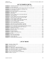
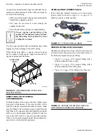
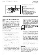
FIGURE 13 -
PROPER LIFTING WITH SHACKLE AT
LIFTING LUG
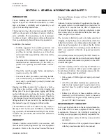
FIGURE 14 -
PROPER LIFTING WITH BASE RAIL
LD13766
PREPARING THE SITE
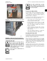
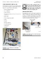
Do not weld or use torches on the ex-
terior or interior of the AHU housing.
The housing contains polyurethane in-
sulation, which, under combustion, will
produce harmful, toxic gases resulting in
personal injury or death.
Never use silicone caulk/sealant in or
on any AHU.
If the AHU has HEPA filters, the filter
frames, bulkheads, and segment panels
are factory sealed, and must remain sealed
to prevent air bypass.
Clearance for Outdoor AHUs
Locate the AHU away from building flue stacks or
exhaust ventilators to prevent possible introduction
of contaminated air through the outside air intakes as
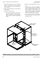
To make sure that the AHU fits properly into the se-
lected location, use the following instructions.
• Allow sufficient space around the AHU to remove
the access panels and various parts.
•
Provide a minimum clearance equal to the width
of the AHU plus 6 in. on one side to remove the
coil or fan assembly. Consider the coil access
panel for coil removal.
•
Add the dimensions of the pipe chase, air hoods,
ducts, control/electrical panels, etc. to meet mini-
mum clearances.
•
Allow any additional clearances as required by
local and National Electrical Codes (NEC).
Mounting the Outdoor AHU
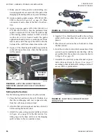
Install AHUs to provide enough elevation for properly
designed condensation traps as discussed under
The area of the roof on which the curb is to be installed
must be structurally adequate to support the combined
weight of curb, AHU, and system fluids. With these
combined weights in place, the resting surface for the
AHU MUST be flat and level.
Concrete pads may not be as flat as they should be.
Shimming and/or grouting may be necessary. Whether
under the AHU base or curb, the AHU base needs to be
on a flat plane.

