JOHNSON CONTROLS
42
FORM 102.20-N1
ISSUE DATE: 7/06/2016
SECTION 3 - HANDLING, STORAGE, AND INSTALLATION
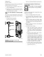
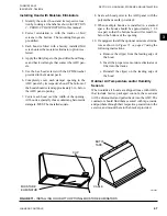
FIGURE 60 -
REMOVE AND REPOSITION
SHIPPING SPLIT ANGLE
LD14097
8.
Attach the come-a-longs to the far end of the first
section.
9. Start pulling the sections together. Pull evenly on
both sides.
a. Make sure all electrical or control wires or
tubes are clear.
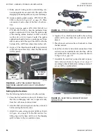
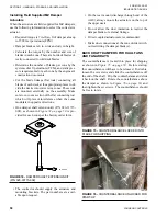
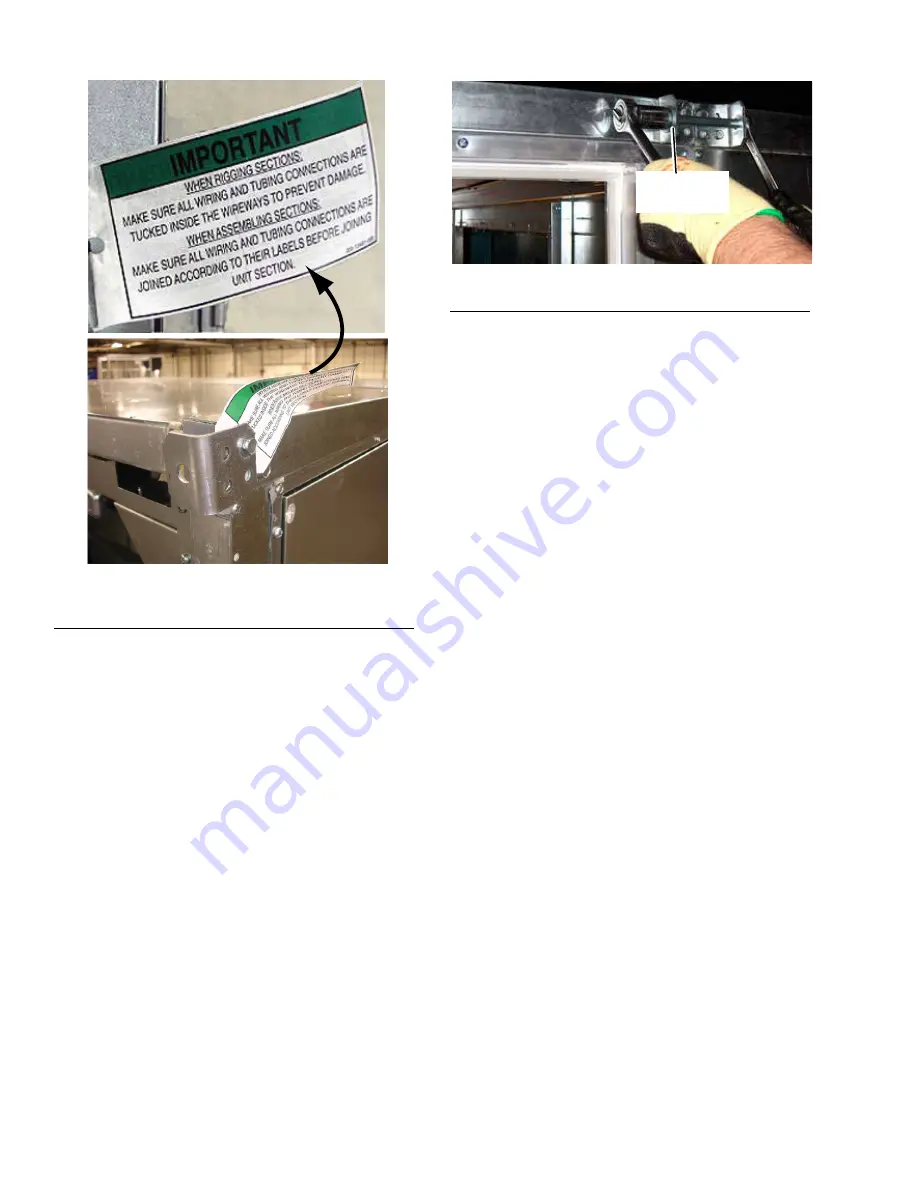
b. Guide the top raceways
together by placing
rods or drift pins through the holes in the top
guide angles. When the raceways are togeth-
er, install the long bolts provided as shown in
.
FIGURE 61 -
BRING SHIPPING SPLITS TOGETHER
LD13775
SHIPPING-
SPLIT
c. Guide the bottom raceway/base rails togeth-
er, using rods or drift pins through the holes
in the lifting lugs on opposite sections simul-
taneously.
d. If there is any difficulty aligning the sections,
due to racking of one section or the other, use
a come-a-long diagonally on the inside of
that section at the shipping split or across the
tops of the opposite sections.
e. If there is any difficulty aligning the sections
due to the top and bottom not pulling to-
gether simultaneously, apply shims under the
sections as needed to compensate for uneven
placement area.
10. Complete pulling the sections together, using the
come-a-longs. The bolts hold the sections tight af-
ter they are pulled together.
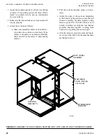
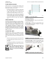
11. Fasten the bottom lifting lugs together with the
1/2 in. x 5-1/2 in. bolts in fastener packet (P/N
386-03418-000) as shown in
12. Fasten the top raceway bracket with the 1/2 in. x
5-1/2 in. bolts in fastener packet (P/N 386-03418-
000).


