JOHNSON CONTROLS
75
SECTION 3 - HANDLING, STORAGE, AND INSTALLATION
FORM 102.20-N1
ISSUE DATE: 7/06/2016
3
Hot and Chilled Water Coils
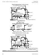
1. Connect the water supply to the header connec-
tion on the leaving air side of the coil to achieve
the counter flow of water and air. The return pipe
will be connected to the remaining coil connec-
tion.
2. Install an air vent in place of the top pipe plug on
the return header. To provide for drainage, install
a drain line and shutoff valve in the supply near
the coil, or in place of the plug in the supply con-
nection as shown in
Water Coil Performance
Full steam pressure of water flow must be
supplied at all times - modulating valves
must not be used. A modulating steam
valve or preheat coil can actually cause
the coil to retain condensate due to a re-
duced pressure in the coil thus exposing
condensate in the tubes to freezing condi-
tions. With modulating steam below 5 psig
(valve closure) the steam may not be fully
distributed in all of the tubes in the coil,
causing the outer tube to cool abnormally.
This will create thermal stress that can
lead to possible "outer tube failure".
The temperature rise of the air (hot water coil) or tem-
perature fall of the air (chilled water coil) leaving the
coil is dependent on the:
• Airflow across the coil,
• Gallons of water flow through the coil, and
•
Entering water temperature into the coil.
Consult the job submittal form for more information.
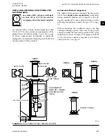
FIGURE 118 -
CHILLED WATER COIL CONNECTIONS EXAMPLE - (NOT FOR CONSTRUCTION)
LD12470
VENT
RETURN
RETURN
SUPPLY
SUPPLY
COIL
COIL
PT
PLUG
DRAIN
UNION
GLOBE
VALVE
GATE
VALVE
PT
PLUG
GATE VALVE W/
HOSE BIB
UNION
GLOBE
VALVE
REDUCING
TEE
CHILLED
WATER
SUPPLY
CHILLED
WATER
RETURN
3 WAY CONTROL VALVE
ECCENTRIC
REDUCER
STRAINER

