JOHNSON CONTROLS
26
FORM 102.20-N1
ISSUE DATE: 7/06/2016
SECTION 3 - HANDLING, STORAGE, AND INSTALLATION
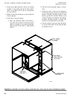
FIGURE 15 -
MINIMUM SERVICE CLEARANCES
LD6326-4
MIN. CLEARANCE DIMENSIONS
A
B
C
D
E
F
G
H
Fan Section
Coil Section
Face and Bypass Damper Section
Filter Section - Door should open 180°
Inlet Section
Rain Hood (add unit width or length)
Pipe Chase Enclosure (add to unit width)
Coil Access Panel on Outdoor Unit
(allow clearance = to unit width)
A
B C D
E
F
G
H
24"
24"
24"
UNIT WIDTH + 6 IN.
Assembling the Johnson Controls Provided
Curb
The curb, which supports the AHU, will be shipped
unassembled, and requires assembly on the job site.
Assembly drawings and a hardware package, which
includes a nailer and gasket
,
are shipped with each
curb. All other parts such as wood or fiber cant strips,
roofing felts and material, caulking, and curb-to-roof
fasteners are field supplied.
If there are questions about the number of curb parts or
assembling the curb, notify a Johnson Controls Field
Service Office immediately.
Use the following instructions to assemble the curb:
1. Unpack the shipping package. Layout the parts
according to the exploded views.
2. Layout all channel pieces as shown in
Make certain that all channel tabs
are located on inside of the mating channel. and
that all curb walls, accessories, and flanges, which
may have been distorted in handling, are straight-
ened before assembly.
3. Attach the curb walls together to form rectangular
perimeter as shown, leaving bolts loose. After the
curb is set in place, ensure proper consideration
has been given to the air duct openings through
the roof.
4. The curb installation drawing shows a gasket that
is mounted between the curb and the unit as shown
in
. This gasket is shipped
with the curb parts. Install the curb gasket before
setting the AHU on the curb. The gasket forms an
air seal between the AHU and the curb and serves
as a dampener, preventing metal-to-metal contact
between the AHU and curb. However, the gasket
should not be used as a vibration isolator where
the prevention of noise and vibration transmission
into the building is critical.
When the AHU is shipped in skids,
replace the curb gasket with the caulk
provided by contractor.
5. After verifying the curb is square and level, tight-
en all bolts, and then anchor appropriately. DO
NOT tighten the bolts after anchoring because the
curb will be pulled, twisted, and torqued out of
square.
6. Mark the exact location for the pipe chase curb.
Drill and assemble the pipe chase curb. The job
submittal drawing package contains a curb draw-
ing that shows the dimensions of the curb and pipe
chase.
7. Insulate and roof the curb as required. Refer to
Sheet Metal and Air Conditioning Contractors
National Association (SMACNA)
for counter
flash information.
Steel Frame
When a steel frame is used to support the AHU, it must
be level, flat without uneven steel frame joints, and
support the AHU around the full perimeter. As a gen-
eral rule, cross members should be placed every 96 in.,
in addition to each shipping split.


