JOHNSON CONTROLS
44
FORM 102.20-N1
ISSUE DATE: 7/06/2016
SECTION 3 - HANDLING, STORAGE, AND INSTALLATION
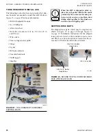
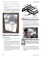
3/8 in. Lock Nut
3/8 x 3/4 in. Button
Head Screw
3/8 x 3/4 in. Button
Head Screw
FIGURE 66 -
SECOND TIER TIE-DOWN FASTENER
PACK (P/N 386-03419-000)
LD11029a
1. Verify the correct sections and orientation of the
top and bottom tiers.
2. Remove cross brace(s) (shipping supports) from
the top tier.
3. Remove the plastic shipping covers and supports.
4. Make sure all wiring and/or control tubing con-
nection pigtails are secured out of the path of the
mating surfaces to prevent damage during rigging.
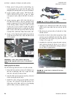
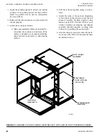
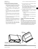
5. Make sure the neoprene gasket (P/N 028-15954-
010) is properly installed on the bottom tier. If the
top tier is shorter in the direction of airflow than
the bottom tier, apply the gasket material on the
top panel of the bottom tier from raceway to race-
way, but not on top of the raceways as shown in
FIGURE 67 -
APPLY GASKETS TO TOP PANEL ON
BOTTOM TIER
LD09690
TOP TIER
TOP LEFT
RACEWAY
TOP PANEL
BOTTOM TIER
TOP RIGHT
RACEWAY
6. Apply the second layer of gasket (P/N 028-15954-
010) over top of the gasket applied in Step 5, but
include the raceways.
Steps
are necessary
because the top panel of the bottom tier is slightly
recessed below the height of its raceways.
7. If the top tier has shipping splits, refer to
ing Indoor Solution XT AHU on page 39
for the
correct assembly procedure.
Make sure all of the electrical or control
wires or tubes in both tiers are clear.
8. Install four shackles, one in each bottom corner
connector or raceway lifting lug. Refer to the
proper lifting procedure for the specific shackles
Proper Lifting with Shackles on page 24
.
9. Fasten the sling/chain to the shackles and the oth-
er end of the sling/chain to the spreader bar (as
needed).
10. Lift the top tier assembly with a crane or overhead
lift.
11. Feed the electrical and control connections from
the top tier to bottom tier, and make sure that they
will be accessible after the sections are joined. If
any connections will not be accessible, assemble
the electrical connectors and/or pneumatic tubes
according to the labels before joining the top and
bottom tiers.
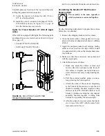
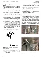
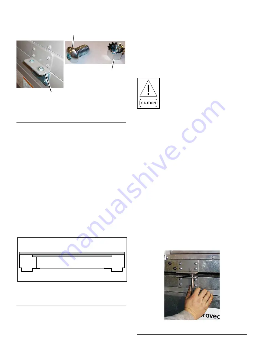
12. Lower the top tier onto bottom tier so that mount-
ing brackets mate. Guide the brackets together,
using rods or drift pins through the bolt holes as
shown in
FIGURE 68 -
GUIDE BRACKETS TOGETHER
LD09626

