JOHNSON CONTROLS
45
SECTION 3 - HANDLING, STORAGE, AND INSTALLATION
FORM 102.20-N1
ISSUE DATE: 7/06/2016
Carefully place each section of the top tier without dis-
turbing the gaskets on the bottom tier.
13. Secure the top tier to bottom tier with 3/8 in. x
0.75 in. allen head bolts.
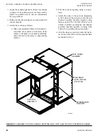
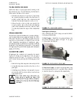
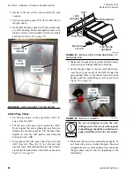
14. Install the corner connector hole plugs (P/N 021-
19568-000) as shown in
onto the bottom raceway corners.
Lights for Tiered Solution XT AHU (If Appli-
cable)
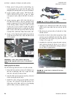
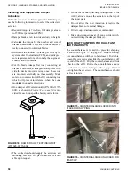
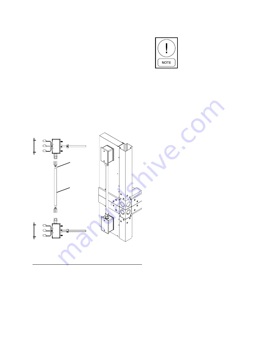
If the AHU is equipped with lights, the following parts
are shipped loose on a tiered unit, as shown in
•
Conduit (P/N 025-39024-001)
•
SJO Cord (P/N 025-35746-01)
JUMPER
FIGURE 69 -
SOLUTION XT LIGHTS TIER
TRANSITION DRAWING
LD16602
CONDUIT
Assembling the Solution XT End Channel
Shipping Split
The assembly is the same regardless
which sections are connected together.
Use the following instructions to prepare the sections
before they are attached.
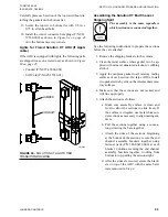
1. Remove the shipping brackets in the corners.
2. Clean the metal surface where gasket is to be ap-
plied with mineral denatured alcohol or rubbing
alcohol.
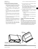
3. Apply the neoprene gasket to all raceway mating
surfaces of each section. On large AHUs, install
two gaskets side by side on the intermediate race-
way surfaces.
4. Make sure that the sections are not racked, and
will line up properly.
5. Attach the sections as follows:
a. Make sure assembly surface is clean and
level to allow the sections to slide freely. If
the surface is irregular, use metal shims un-
der sections as necessary to align mating sur-
faces.
b. Pull the sections together using a come-a-
long, drawing the base together.
c. Attach the sides of the sections. Beginning
at the bottom of the sections, secure the end
channel assembly brackets together using
fastener pack (P/N 386-03419-000) at each
bracket. Continue securing the end channel
assembly brackets together, working from
bottom to top, pulling the sections tight.
d. After the sides are secured, secure the brack-
ets on top of the AHU with the same hard-
ware removed in
Step
4
.


