background image

5532522-UIM-B-0619

4

Johnson Controls Ducted Systems

SECTION II: DUCTWORK

DUCTWORK GENERAL INFORMATION

The duct system’s design and installation must:

1. Handle an air volume appropriate for the served space and within

the operating parameters of the furnace specifications.

2. Be installed in accordance of National Fire Protection Association

as outlined in NFPA standard 90B (latest editions) or applicable
national, provincial, state, and local fire and safety codes.

3. Create a closed duct system. When a furnace is installed so that

the supply ducts carry air circulated by the furnace to areas outside
the space containing the furnace, the return air shall also be han-
dled by a duct(s) sealed to the furnace casing and terminating out-
side the space containing the furnace.

4. Complete a path for heated or cooled air to circulate through the air

conditioning and heating equipment and to and from the condi-
tioned space.

When the furnace is used with a cooling coil, the coil must be installed
parallel with, or in the supply air side of the furnace to avoid condensa-
tion in the primary heat exchanger. When a parallel flow arrangement is
used, dampers or other means used to control airflow must be ade-
quate to prevent chilled air from entering the furnace. If manually oper-
ated, the damper must be equipped with means to prevent the furnace
or the air conditioner from operating unless the damper is in full heat or
cool position.
When replacing an existing furnace, if the existing plenum is not the
same size as the new furnace then the existing plenum must be
removed and a new plenum installed that is the proper size for the new
furnace. If the plenum is shorter than 12” (30.5 cm) the turbulent air flow
may cause the limit controls not to operate as designed, or the limit con-
trols may not operate at all.
The duct system is a very important part of the installation. 

If the duct

system is improperly sized the furnace will not operate properly.

The ducts attached to the furnace plenum, should be of sufficient size
so that the furnace operates at the specified external static pressure
and within the air temperature rise specified on the nameplate.

If a matching cased indoor coil is used, it may be placed directly on the
furnace outlet and sealed to prevent leakage. If an uncased indoor coil
with a thermoplastic drain pan is to be installed in the upflow/horizontal
configuration, then extra 2” minimum spacing may be needed to ensure
against drain pan distortion.
On all installations without a coil, a removable access panel is recom-
mended in the outlet duct such that smoke or reflected light would be
observable inside the casing to indicate the presence of leaks in the
heat exchanger. This access cover shall be attached in such a manner
as to prevent leaks.

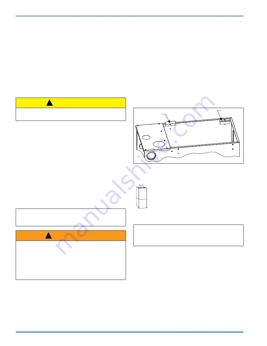
DUCT FLANGES

Four flanges are provided to attach ductwork to the furnace. These
flanges are rotated down for shipment. In order to use the flanges,
remove the screw holding an individual flange, rotate the flange so it is
in the upward position and reinstall the screw then repeat this for all 4
flanges.
If the flanges are not used, they must remain in the rotated down posi-
tion as shipped.

DUCTWORK INSTALLATION AND SUPPLY PLENUM 

CONNECTION

Attach the supply plenum to the furnace outlet. The use of
an approved flexible duct connector is recommended on all
installations. This connection should be sealed to prevent
air leakage. The sheet metal should be crosshatched to
eliminate any popping of the sheet metal when the indoor
fan is energized.

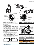
COIL INSTALLATION

The indoor coil must be mounted on the supply side of the furnace as
shown in Figure 2. Refer to the Installation Instructions provided with
each indoor coil.

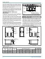
 CAUTION

The cooling coil must be installed in the supply air duct, downstream
of the furnace. Cooled air may not be passed over the heat
exchanger.

IMPORTANT:  

The minimum plenum height is 12” (30.5 cm). The fur-

nace will not operate properly on a shorter plenum height. The mini-
mum recommended rectangular duct height is 4” (10.1 cm) attached
to the plenum.

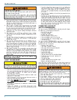
 WARNING

The duct system must be properly sized to obtain the correct airflow
for the furnace size that is being installed.
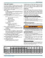
Refer to Table 4 or the furnace rating plate for the correct rise range
and static pressures.
If the ducts are undersized, the result will be high duct static pres-
sures and/or high temperature rises which can result in a heat
exchanger OVERHEATING CONDITION. This condition can result in
premature heat exchanger failure, which can result in personal injury,
property damage, or death.

!

!

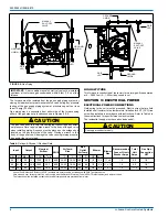
 FIGURE 1: 

Duct Attachment

IMPORTANT:  

On all installations without an indoor coil, a removable

access panel is recommended in the outlet duct such that smoke or
reflected light would be observable inside the casing to indicate the
presence of leaks in the heat exchanger. This access cover shall be
attached in such a manner as to prevent leaks.

)DFWRU\
LQVWDOOHG

)RUGXFWDWWDFKPHQW
LIQHHGHG

$

Summary of Contents for TL8E

Page 1: ...ment closet alcove attic recreation room or garage and are also ideal for commercial applications All units are factory assembled wired and tested to assure safe dependable and economical installation...

Page 2: ...talling and servicing heating equipment can be hazardous due to the electrical components and the gas fired components Only trained and qualified personnel should install repair or service gas heating...

Page 3: ...spection by the carrier s agent should be made in writing Also before installation the unit should be checked for screws or bolts which may have loosened in transit There are no shipping or spacer bra...

Page 4: ...rizontal configuration then extra 2 minimum spacing may be needed to ensure against drain pan distortion On all installations without a coil a removable access panel is recom mended in the outlet duct...

Page 5: ...rt with required service accessibility HORIZONTAL APPLICATION ATTIC INSTALLATION This appliance is certified for line contact when the furnace is installed in the horizontal left or right position The...

Page 6: ...s must be level to ensure proper and quiet fur nace operation When suspending the furnace use a secure platform constructed of plywood or other building materials secured to the floor or ceiling joist...

Page 7: ...minimum sizes listed in these instructions and in the codes The furnace rating plate and the instructions in this section specify the type of gas approved for this furnace only use those approved gase...

Page 8: ...latest edition and all local codes The furnace shall be installed so that the electrical components are protected from water FIGURE 9 Gas Piping GROUND UNION DRIP LEG MANUAL SHUT OFF VALVE GROUND UNIO...

Page 9: ...set in the OFF position and the main electrical source disconnected connect the thermostat wiring from the wiring connections on the thermostat to the low voltage terminal block on the integrated furn...

Page 10: ...rmostat Chart Single Stage HP with Single Stage Furnaces 6LQJOH 6WDJH R1R XUQDFH 6LQJOH 6WDJH HDW 3XPS 6HFRQG 6WDJH HDW DQ 5 9ROW RW LUVW 6WDJH HDW 9ROW RPPRQ 9ROW RPPRQ 5 9ROW RW 6HFRQG 6WDJH RPSUHVV...

Page 11: ...FURNACE IS NOT TO BE VENTED INTO AN UNLINED MASONRY CHIMNEY 2 This furnace must be vented into a fire clay tile lined masonry chim ney only if a source of dilution air is provided such as by common v...

Page 12: ...ind Such means shall not reduce the required free area of the air supply opening 7 An air supply inlet opening from the outdoors shall be located not less than 12 30 5 cm above the outside grade level...

Page 13: ...d that the ground union be loosened until the odor of gas is detected When gas is detected immediately retighten the union and check for leaks Allow five minutes for any gas to dissipate before contin...

Page 14: ...occur as follows a The induced draft blower will start and will run for several sec onds in order to bring fresh combustion air into the combustion chamber Then the induced draft blower will shut off...

Page 15: ...22 164 327 818 64 56 112 281 23 157 313 783 66 54 109 273 24 150 300 750 68 53 106 265 25 144 288 720 70 51 103 257 26 138 277 692 72 50 100 250 27 133 267 667 74 48 97 243 28 129 257 643 76 47 95 237...

Page 16: ...n gas valve 2 Turn gas and electrical supplies on and follow the operating instruc tions to place the unit back in operation 3 Adjust manifold pressure by adjusting gas valve regulator screw for the a...

Page 17: ...to 120 seconds The fan off setting must be long enough to adequately cool the furnace but not so long that cold air is blown into the heated space The fan off timing may be adjusted by positioning th...

Page 18: ...alve This is an automatic reset control that provides over temperature protection due to reduced airflow This may be caused by 1 A dirty filter 2 If the indoor fan motor should fail 3 Too many supply...

Page 19: ...condition is not corrected the ignition control will lock out for 60 minutes During burner operation a momentary loss of power for 50 milliseconds or longer will de energize the gas valve When the pow...

Page 20: ...e if a temporary condition exists causing a furnace malfunction An example of this is a temporary interruption in gas supply that would prevent the furnace from lighting The control will keep trying t...

Page 21: ...FICE BURNER SIGHT GLASS OVAL 2 Req d GASKET FOAM Door 1 5 ft req d GASKET INTAKE PAN PLUG VENT HOLE BRACKET DOOR WIRING HARNESS FERRULE 3 Req d GROMMET 3 Req d MOTOR MOUNT TUBING SILICON DIAGRAM WIRIN...

Page 22: ...5532522 UIM B 0619 22 Johnson Controls Ducted Systems SECTION XI WIRING DIAGRAM FIGURE 20 Wiring Diagram...

Page 23: ...stallation Instructions and Local Code Gas piping is connected including drip leg Supply plenum and return air are connected Filter Size Vent system is connected Thermostat wiring is complete Thermost...

Page 24: ...ure in w c Return Static in w c after Air Side Heating Air Side Cooling Air Side Continuous Fan Clean Up Give owner the owner s manual provided Explain thermostat use and programming if applicable to...

Reviews: