5532522-UIM-B-0619
Johnson Controls Ducted Systems
3
CODES AND STANDARDS
Follow all national, local codes and standards in addition to this installa-
tion manual. The installation must comply with regulations of the serv-
ing gas supplier, local building, heating, plumbing, and other codes. In
absence of local codes, the installation must comply with the national
codes listed below and all authorities having jurisdiction.
In the United States and Canada, follow all codes and standards for the
following, using the latest edition available:
STEP 1 -Safety
• US: National Fuel Gas Code (NFGC) NFPA 54/ANSI Z223.1 and
the Installation Standards, Warm Air Heating and Air Conditioning
Systems ANSI/NFPA 90B
• CANADA: CAN/CGA-B149.1 National Standard of Canada. Natu-
ral Gas and Propane Installation Codes (NSCNGPIC)
STEP 2 -General Installation
• US: Current edition of the NFGC and NFPA 90B. For copies, con-
tact the
National Fire Protection Association Inc.
Batterymarch Park
Quincy, MA 02269
or for only the NFGC, contact the
American Gas Association,
400 N. Capital, N.W.
Washington DC 20001
or www.NFPA.org
• CANADA: NSCNGPIC. For a copy contact:
Standard Sales, CSA International
178 Rexdale Boulevard
Etobicoke, (Toronto) Ontario Canada M9W 1RS
STEP 3 -Combustion and Ventilation Air
• US: Section 5.3 of the NFGC, air for Combustion and Ventilation
• CANADA: Part 7 of NSCNGPIC, Venting Systems and Air Supply
for Appliances
STEP 4 -Duct Systems
• US and CANADA: Air Conditioning Contractors Association
(ACCA) Manual D, Sheet Metal and Air Conditioning Contractors
Association National Association (SMACNA), or American Soci-
ety of Heating, Refrigeration, and Air Conditioning Engineers
(ASHRAE) 1997 Fundamentals Handbook Chapter 32.
STEP 5 -Acoustical Lining and Fibrous Glass Duct
• US and CANADA: Current edition of SMACNA and NFPA 90B as
tested by UL Standard 181 for Class I Rigid Air Ducts
STEP 6 -Gas Piping and Gas Pipe Pressure Testing
• US: NFGC; chapters 2, 3, 4, & 9 and National Plumbing Codes
• CANADA: NSCNGPIC Part 5
STEP 7 -Electrical Connections
• US: National Electrical Code (NEC) ANSI/NFPA 70
• CANADA: Canadian Electrical Code CSA C22.1
These instructions cover minimum requirements and conform to exist-
ing national standards and safety codes. In some instances these
instructions exceed certain local codes and ordinances, especially
those who have not kept up with changing residential and non-HUD
modular home construction practices. These instructions are required
as a minimum for a safe installation.
INSPECTION
As soon as a unit is received, it should be inspected for possible dam-
age during transit. If damage is evident, the extent of the damage
should be noted on the carrier’s freight bill. A separate request for
inspection by the carrier’s agent should be made in writing. Also, before
installation, the unit should be checked for screws or bolts which may
have loosened in transit. There are no shipping or spacer brackets
which need to be removed from the interior of this unit.
FURNACE LOCATION AND CLEARANCES
The furnace shall be located using the following guidelines:
1. Where a minimum amount of air intake/vent piping and elbows will
be required.
2. As centralized with the air distribution as possible.
3. Where adequate combustion air will be available (particularly when
the appliance is not using outdoor combustion air).
4. Where it will not interfere with proper air circulation in the confined
space.
Installation in freezing temperatures:
1. Furnace shall be installed in an area where ventilation facilities pro-
vide for safe limits of ambient temperature under normal operating
conditions.
2. Do not allow return air temperature to be below 55ºF (13ºC) for
extended periods. To do so may cause condensation to occur in the
main heat exchanger, leading to premature heat exchanger failure.
Clearances for access/service:
Ample clearances should be provided to permit easy access to the unit.
The following minimum clearances are recommended:
1. Twenty-four (24) inches (61 cm) between the front of the furnace
and an adjacent wall or another appliance, when access is required
for servicing and cleaning.
2. Eighteen (18) inches (46 cm) at the side where access is required
for passage to the front when servicing or for inspection or replace-
ment of flue/vent connections.
In all cases, accessibility clearances shall take precedence over clear-
ances for combustible materials where accessibility clearances are
greater.
Installation in a residential garage:
A gas-fired furnace for installation in a residential garage must be
installed so the burner(s) and the ignition source are located not less
than 18” (46 cm) above the floor, and the furnace must be located or
protected to avoid physical damage by vehicles.
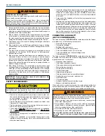
WARNING
a. Improper installation in an ambient below 32ºF (0ºC) could cre-
ate a hazard, resulting in damage, injury or death.
!
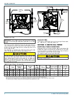
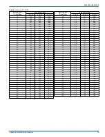
Table 1:
Unit Clearances to Combustibles (All Dimensions in Inches, and All Surfaces Identified with the Unit in an Upflow Configuration)
Application
Top
Front
Rear
Left
Side
Right
Side
Flue
Floor/
Bottom
Closet
Alcove
Attic
Line
Contact
In. (cm)
In. (cm)
In. (cm)
In. (cm)
In. (cm)
In. (cm)
Upflow
1 (2.5)
1 (2.5)
0 (0.0)
0 (0.0)
0 (0.0)
6 (15.2)
Combustible
Yes
Yes
Yes
No
Upflow B-Vent
1 (2.5)
1 (2.5)
0 (0.0)
0 (0.0)
0 (0.0)
1 (2.5)
Combustible
Yes
Yes
Yes
No
Horizontal
1 (2.5)
1 (2.5)
0 (0.0)
0 (0.0)
0 (0.0)
6 (15.2)
Combustible
No
Yes
Yes
Yes
1
1. Line contact only permitted between lines formed by the intersection of the rear panel and side panel (top in horizontal position) of the furnace jacket and building
joists, studs, or framing.
Horizontal B-Vent
1 (2.5)
1 (2.5)
0 (0.0)
0 (0.0)
0 (0.0)
1 (2.5)
Combustible
No
Yes
Yes
Yes
1


