FORM 150.66-NM2
ISSUE DATE: 09/25/2020
129
JOHNSON CONTROLS
8
CAPACITY CONTROL
To initiate the start sequence of the chiller, all run
permissive inputs must be satisfied (flow/remote start/
stop switch), and no chiller or system faults exist.
The first phase of the start sequence is initiated by the
Daily Schedule Start or any Remote Cycling Device. If
the unit is shut down on the daily schedule, the chilled
water pump microboard contacts (TB5 3-4) will close
to start the pump when the daily schedule start time
has been reached. Once flow has been established and
the flow switch closes, capacity control functions are
initiated, if the remote cycling contacts wired in series
with the flow switch are closed.
It should be noted that the chilled water pump contacts
(TB5 3-4) are not required to be used to cycle the chilled
water pump. However, in all cases the flow switch must
be closed to allow unit operation.
The control system will evaluate the need for cooling
by comparing the actual leaving or return chilled liquid
temperature to the desired setpoint, and regulate the
leaving or return chilled liquid temperature to meet that
desired setpoint.
SUCTION PRESSURE LIMIT CONTROLS
The anticipatory controls are intended to prevent the
unit from ever actually reaching a low-pressure cutout.
Loading is prevented, if the suction pressure drops
below 1.15 x suction pressure cutout. Load may reoccur
after suction pressure rises above the unload point and
a period of one minute elapses. This control is only
operable if the optional suction pressure transducers
are installed.
DISCHARGE PRESSURE LIMIT CONTROLS
The discharge pressure limit controls unload a system
before it reaches a safety limit due to high load or dirty
condenser coils. The micro monitors discharge pressure
and unloads a system, if fully loaded, by one compressor
when discharge pressure exceeds the programmed cutout
minus 15 psig. Reloading will occur when the discharge
pressure on the affected system drops to 85% of the
unload pressure and 10 minutes have elapsed.
This control is only applicable if optional discharge
pressure transducers are installed.
LEAVING CHILLED LIQUID CONTROL
The setpoint, when programmed for Leaving Chilled
Liquid Control, is the temperature the unit will control
to /- the (control) cooling range. The Setpoint
High Limit is the Setpoint plus the Cooling Range.
The Setpoint Low Limit is the Setpoint minus the
Cooling Range.
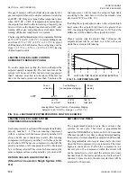
should be utilized to aid in
understanding the following description of Leaving
Chilled Liquid Control.
If the leaving chilled liquid temperature is above the
Setpoint High Limit, the lead compressor on the lead
system will be energized along with the liquid line
solenoid. Upon energizing any compressor, the 60
second Anti-Coincidence timer will be initiated to
prevent multiple compressors from turning on.
If after 60 seconds of run-time the leaving chilled liquid
temperature is still above the Setpoint High Limit,
the next compressor in sequence will be energized.
Additional compressors will be energized at a rate of
once every 60 seconds if the chilled liquid temperature
remains above the Setpoint High Limit and the chilled
liquid temperature is dropping less than 3°F/min. The
lag system will not be allowed to start a compressor until
the lead system has run for 5 minutes.
If the chilled liquid temperature falls below the Setpoint
High Limit but is greater than the Setpoint Low Limit,
loading and unloading do not occur. This area of control
is called the control range.
If the chilled liquid temperature drops to between
Setpoint Low Limit and 0.5°F (.28°C) below the
Setpoint Low Limit, unloading (a compressor turns off)
occurs at a rate of 1 every 60 seconds. If the chilled liquid
temperature falls to a value greater than 0.5°F (.28°C)
below the Setpoint Low Limit but not greater than 1.5°F
(.83°C) below the Setpoint Low Limit, unloading occurs
at a rate of 30 seconds. If the chilled liquid temperature
falls to a value greater than 1.5°F (.83°C) below the
Setpoint Low Limit, unloading occurs at a rate of 20
seconds. If the chilled liquid temperature falls below
1°F above the low chilled liquid temperature cutout,
unloading occurs at a rate of 10 seconds.
For leaving chilled liquid temperature setpoint and
control range combinations that result in the low limit of
the control range being below 40.0ºF, the low limit will
be reset to 40.0ºF and the difference will be added to the
high limit. This will result in a control range the same
size as programmed but not allow the unit to run below
40.0ºF. This control will not affect glycol chillers.
SECTION 8 - UNIT OPERATION
Summary of Contents for YCAL0012EC
Page 12: ...JOHNSON CONTROLS 12 FORM 150 66 NM2 ISSUE DATE 09 25 2020 THIS PAGE INTENTIONALLY LEFT BLANK...
Page 16: ...JOHNSON CONTROLS 16 FORM 150 66 NM2 ISSUE DATE 09 25 2020 THIS PAGE INTENTIONALLY LEFT BLANK...
Page 98: ...JOHNSON CONTROLS 98 FORM 150 66 NM2 ISSUE DATE 09 25 2020 THIS PAGE INTENTIONALLY LEFT BLANK...
Page 142: ...JOHNSON CONTROLS 142 FORM 150 66 NM2 ISSUE DATE 09 25 2020 THIS PAGE INTENTIONALLY LEFT BLANK...
Page 165: ...FORM 150 66 NM2 ISSUE DATE 09 25 2020 165 JOHNSON CONTROLS NOTES...


