YORK INTERNATIONAL
104
The micro panel is capable of supplying a printout of
chiller conditions or fault shutdown information at any
given time. This allows operator and service personnel
to obtain data and system status with the touch of the
keypad. In addition to manual print selection, the micro
panel will provide an automatic printout whenever a fault
occurs. Detailed explanation of the print function is given
under “Print Key” located in the Keypad and Display sec-
tion.
YORK recommends the field tested WEIGH-TRONIX
model 1220 printer (or former IMP 24). This is a com-
pact low cost printer that is ideal for service work and
data logging.
The WEIGH-TRONIX printer can be obtained by con-
tacting WEIGH-TRONIX for purchase information at:
WEIGH-TRONIX
2320 Airport Blvd.
Santa Rosa, CA 95402
Phone: 1-800-982-6622 or 1-707-527-5555
(International Orders Only)
The part number for the printer that is packaged specifi-
cally for YORK is P/N 950915576. The cable to connect
the printer can either be locally assembled from the parts
listed, or ordered directly from WEIGH-TRONIX under
part number 287-040018.
Parts
The following parts are required:
1. WEIGH-TRONIX model 1220 printer.
2. 2.25" (5.7cm) wide desk top calculator paper.
3. 25 ft. (7.62m) maximum length of Twisted Pair
Shielded Cable (minimum 3 conductor), #18 AWG
stranded, 300V minimum insulation.
4. One 25 pin Cannon connector and shell.
Connector: Cannon P/N DB-25P or equivalent.
Shell: Cannon P/N DB-C2-J9.
Assembly and Wiring
All components should be assembled and wired as
shown in Figure 10. Strip the outside insulation back
several inches and individual wires about 3/8” (9.5 mm)
to connect the cable at the Microboard. Do not connect
the shield at the printer-end of the cable.
Obtaining a Printout
A printout is obtained by pressing the “PRINT” key on
the keypad and then pressing either the “OPER DATA”
key or “HISTORY” key.
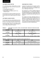
FIG. 10 – PRINTER TO MICROBOARD ELECTRICAL CONNECTIONS
LD03843
Service and Troubleshooting
OPTIONAL PRINTER INSTALLATION
Summary of Contents for YCAL0014SC
Page 115: ...YORK INTERNATIONAL 115 FORM 150 62 NM1 This page intentionally left blank 4...
Page 116: ...YORK INTERNATIONAL 116 ELEMENTARY DIAGRAM YCAL0034SC FIG 13 ELEMENTARY DIAGRAM Wiring Diagrams...
Page 119: ...YORK INTERNATIONAL 119 FORM 150 62 NM1 This page intentionally left blank 4...
Page 130: ...APPENDIX 1 DIMENSIONS FIG 19 TYPE CP 1 FIG 20 TYPE CP 2 LD03839 LD03840 Appendix 1 Isolators...
Page 135: ...YORK INTERNATIONAL 135 FORM 150 62 NM1 This page intentionally left blank...


