FORM 150.67-NM2 (209)
129
JOHNSON CONTROLS
7
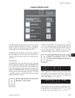
“STATUS” KEY
Unit Status
Pressing the STATUS key will enable the operator to
determine current chiller operating status. The messages
displayed will include running status, cooling demand,
fault status, external cycling device status. The display
will be a single message relating to the highest priority
message as determined by the micro. Status messages
fall into the categories of General Status and Fault
Status.
The following General, Safety, and Warning messages
are displayed when the Status key is pressed. Following
each displayed message is an explanation pertaining to
that particular message.
General Status Messages
In the case of messages which apply to individual
systems, SYS 1 and SYS 2 messages will both be
displayed and may be different. In the case of single
system units, all SYS 2 messages will be blank.
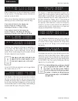
This message informs the operator that the UNIT switch
on the control panel is in the OFF position which will
not allow the unit to run.
The REMOTE CONTROLLED SHUTDOWN message
indicates that either an ISN system or RCC has turned
the unit “OFF”, not allowing it to run.
The DAILY SCHEDULE SHUTDOWN message
indicates that the daily/holiday schedule programmed
is keeping the unit from running.
REMOTE STOP NO RUN PERM shows that either
the
fl
ow switch is open or a remote start/stop contact is
open in series with the
fl
ow switch. These contacts are
connected to J13-5. A 3-second delay is built into the
software to prevent nuisance shutdowns due to erroneous
signals on the run permissive input.
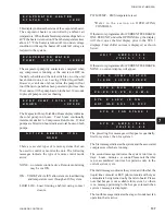
SYS SWITCH OFF tells that the system switch under
OPTIONS is turned “OFF”. The system will not be
allowed to run until the switch is turned back on.
U N I T S W I T C H O F F
S
H
U
T
D
O
W
N
R E M O T E C O N T R O L L E D
S
H
U
T
D
O
W
N
D A I L Y S C H E D U L E
S
H
U
T
D
O
W
N
REMOTE STOP
NO RUN PERM
00066VIP
S Y S 1 S Y S S W I T C H O F F
S Y S 2 S Y S S W I T C H O F F
Summary of Contents for YCAL0019
Page 55: ...FORM 150 67 NM2 209 55 JOHNSON CONTROLS 5 5 ELEMENTARY WIRING DIAGRAM CON T LD12699D...
Page 57: ...FORM 150 67 NM2 209 57 JOHNSON CONTROLS 5 5 ELEMENTARY WIRING DIAGRAM CON T LD12693C...
Page 59: ...FORM 150 67 NM2 209 59 JOHNSON CONTROLS 5 5 ELEMENTARY WIRING DIAGRAM CON T LD 12198...
Page 61: ...FORM 150 67 NM2 209 61 JOHNSON CONTROLS 5 5 LD12702 ELEMENTARY WIRING DIAGRAM CON T...
Page 63: ...FORM 150 67 NM2 209 63 JOHNSON CONTROLS 5 5 LD12696 ELEMENTARY WIRING DIAGRAM CON T...
Page 65: ...FORM 150 67 NM2 209 65 JOHNSON CONTROLS 5 5 CONNECTION WIRING DIAGRAM CON T LD12703B...
Page 67: ...FORM 150 67 NM2 209 67 JOHNSON CONTROLS 5 5 CONNECTION WIRING DIAGRAM CON T LD12697B...


