FORM 150.67-NM2 (209)
15
JOHNSON CONTROLS
2
• Suction pressure cutout setting
• Each system suction pressure
• Discharge pressure (optional)
• Liquid Temperature Reset via a YORK ISN DDC
or Building Automation System (by others) via:
- a pulse width modulated (PWM) input as stan
-
dard.
- a 4-20 milliamp or 0 -10 VDC input with the
optional B.A.S. interface option.
• Anti-recycle timer status for each system
• Anti-coincident system start timer condition
• Compressor run status
• No cooling load condition
• Day, date and time
• Daily start/stop times
• Holiday status
• Automatic or manual system lead/lag control
• Lead system definition
• Compressor starts & operating hours
(each compressor)
• Status of hot gas valves, evaporator heater
and fan operation
• Run permissive status
• Number of compressors running
• Liquid solenoid valve status
• Load & unload timer status
• Water pump status
Provisions are included for: pumpdown at shutdown;
optional remote chilled water temperature reset and
two steps of demand load limiting from an external
building automation system. Unit alarm contacts are
standard.
The operating program is stored in non-volatile
memory (EPROM) to eliminate chiller failure due to
AC powered failure/battery discharge. Programmed
setpoints are retained in lithium battery-backed RTC
memory for 5 years minimum.
* Intensity of Protection European Standard
** International Electrotechnical Commission
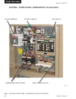
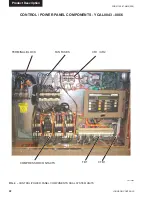
POWER PANEL
Each panel contains:
• Compressor power terminals
• Compressor motor starting contactors per
l.E.C.**
• Control power terminals to accept incoming for
115-1-60 control power
• Fan contactors & overload current protection
The power wiring is routed through liquid-tight
conduit to the compressors and fans.
Summary of Contents for YCAL0019
Page 55: ...FORM 150 67 NM2 209 55 JOHNSON CONTROLS 5 5 ELEMENTARY WIRING DIAGRAM CON T LD12699D...
Page 57: ...FORM 150 67 NM2 209 57 JOHNSON CONTROLS 5 5 ELEMENTARY WIRING DIAGRAM CON T LD12693C...
Page 59: ...FORM 150 67 NM2 209 59 JOHNSON CONTROLS 5 5 ELEMENTARY WIRING DIAGRAM CON T LD 12198...
Page 61: ...FORM 150 67 NM2 209 61 JOHNSON CONTROLS 5 5 LD12702 ELEMENTARY WIRING DIAGRAM CON T...
Page 63: ...FORM 150 67 NM2 209 63 JOHNSON CONTROLS 5 5 LD12696 ELEMENTARY WIRING DIAGRAM CON T...
Page 65: ...FORM 150 67 NM2 209 65 JOHNSON CONTROLS 5 5 CONNECTION WIRING DIAGRAM CON T LD12703B...
Page 67: ...FORM 150 67 NM2 209 67 JOHNSON CONTROLS 5 5 CONNECTION WIRING DIAGRAM CON T LD12697B...


