FORM 150.67-NM2 (209)
153
JOHNSON CONTROLS
7
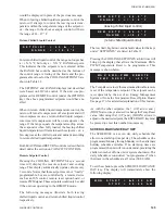
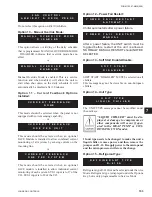
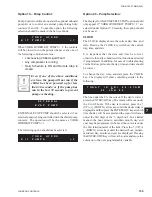
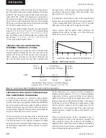
Option 12 – Power Fail Restart:
Chiller auto restarts after a power failure.
After a power failure, the UNIT switch must be
toggled before restart at the unit is allowed.
NORMALLY MANUAL RESTART should NOT BE
SELECTED.
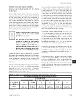
Option 13 – Soft Start Enable/Disable:
SOFT START “DISABLED” MUST be selected on all
chillers.
This message may not be viewable on non-European
chillers.
Option 14 – Unit Type:
The UNIT TYPE message cannot be modi
fi
ed under
the unit keys.
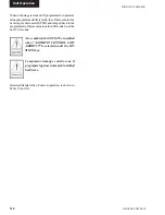
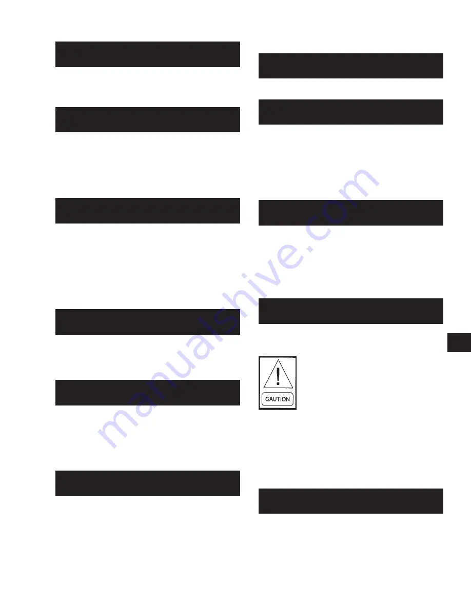
“LIQUID CHILLER” must be dis-
played, or damage to compressors or
other components will occur if oper-
ated in the HEAT PUMP or CON-
DENSING UNIT modes.
If unit type needs to be changed to make the unit a
liquid chiller, remove power and then remove the
jumper on J11-12. Reapply power to the micropanel
and the microprocessor will store the change.
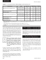
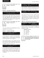
Option 15 – Refrigerant Type:
Refrigerant type R-410A must be selected under Service
Mode. Refrigerant type is displayed under the Options
Key, but is only programmable in Service Mode.
Do not select this option on R-410A chillers.
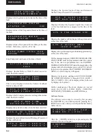
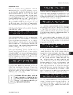
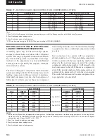
Option 10 – Manual Override Mode:
This option allows overriding of the daily schedule
that is programmed. MANUAL OVERRIDE MODE
– DISABLED indicates that override mode has no
effect.
or
Manual Override Mode is enabled. This is a service
function and when enabled, will allow the unit to
start when shut down on the daily schedule. It will
automatically be disabled after 30 minutes.
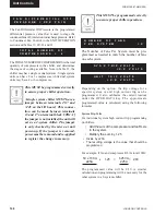
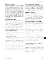
Option 11 – Current Feedback Options
Installed:
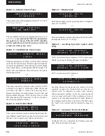
This mode should be selected when the panel is not
equipped with current sensing capability.
or
This mode should be selected when an optional
2ACE Module is installed to allow combined current
monitoring of all systems by sensing current on the
incoming line.
or
This mode should be selected when an optional
2ACE module is installed to allow individual current
monitoring of each system. SYS 1 input is to J7 of the
I/O. SYS 2 input is to J8 of the I/O.
C U R R E N T F E E D B A C K
N O N E
C U R R E N T F E E D B A C K
O N E P E R U N I T
C U R R E N T F E E D B A C K
O N E P E R S Y S T E M
M A N U A L O V E R R I D E M O D E
D
I
S
A
B
L
E
D
M A N U A L O V E R R I D E M O D E
E
N
A
B
L
E
D
F A N C O N T R O L
A M B I E N T & D S C H P R E S S
U N I T T Y P E
L I Q U I D C H I L L E R
R E F R I G E R A N T T Y P E
R – 4 1 0 A
S O F T S T A R T
D
I
S
A B L E D
P O
W E R F A I L R E S T A R T
A
U
T
O
M
A
T I
C
P O
W E R F A I L R E S T A R T
M
A
N
U
A
L
Summary of Contents for YCAL0019
Page 55: ...FORM 150 67 NM2 209 55 JOHNSON CONTROLS 5 5 ELEMENTARY WIRING DIAGRAM CON T LD12699D...
Page 57: ...FORM 150 67 NM2 209 57 JOHNSON CONTROLS 5 5 ELEMENTARY WIRING DIAGRAM CON T LD12693C...
Page 59: ...FORM 150 67 NM2 209 59 JOHNSON CONTROLS 5 5 ELEMENTARY WIRING DIAGRAM CON T LD 12198...
Page 61: ...FORM 150 67 NM2 209 61 JOHNSON CONTROLS 5 5 LD12702 ELEMENTARY WIRING DIAGRAM CON T...
Page 63: ...FORM 150 67 NM2 209 63 JOHNSON CONTROLS 5 5 LD12696 ELEMENTARY WIRING DIAGRAM CON T...
Page 65: ...FORM 150 67 NM2 209 65 JOHNSON CONTROLS 5 5 CONNECTION WIRING DIAGRAM CON T LD12703B...
Page 67: ...FORM 150 67 NM2 209 67 JOHNSON CONTROLS 5 5 CONNECTION WIRING DIAGRAM CON T LD12697B...

