JOHNSON CONTROLS
176
FORM 150.67-NM2 (209)
Unit Operation
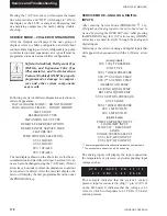
BAS/EMS TEMPERATURE RESET USING
A VOLTAGE OR CURRENT SIGNAL
The Remote Reset Option allows the Control Center
of the unit to reset the chilled liquid setpoint using a
0 - 10VDC input, or a 4-20mA input connected to CTB1
terminals A- and A+. Whenever a reset is called for, the
change may be noted by pressing the Cooling Setpoints
key twice. The new value will be displayed as “REM
SETP = XXX °F.”
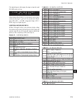
If a
0 - 10VDC
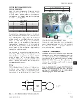
signal is supplied, it is applied to
terminals A+ and A-, and
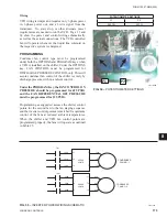
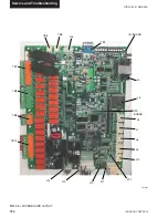
jumper JP1 on the I/O board
must be inserted between pins 2 and 3.
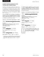
To calculate
the reset chilled liquid setpoint for values between 0VDC
and 10VDC use the following formula:
Setpoint = Local Chilled Liquid Se °Reset
Reset = (DC voltage signal) x (*Max Reset Value)
10
Example:
Local Chilled Liquid Setpoint = 45 °F (7.22 °C)
*Max Reset Value = 20 °F (11.11 °C)
Input Signal = 6VDC
(English)
Reset = 6VDC x 20 °F = 12
°F Reset
10
New Setpoint = 45 °F + 12 °F = 57 °F
(Metric)
Reset = 6VDC x 11. 11 °C = 6.67 °C Reset
10
New Setpoint = 7.22 °C + 6.67 °C = 13.89 °C
*
Max Reset Value is the “Max EMS-PWM Remote Temp. Reset” setpoint
value described in the program ming section under Cooling Setpoints.
Programmable values are from 2 °F to 40 °F (1.11 °C to 11.11
°C).
If a
4-20mA signal is supplied,
it is applied to terminals
A+ and A- and
jumper JP1 on the I/O board must be
installed between pin 1 and 2
. To calculate the chilled
liquid setpoint for values between 4mA and 20 mA use
the following formula:
Setpoint = Local Chilled Liquid Se °Reset
°Reset = (mA signal - 4) x (*Max Reset Value)
16
Example:
Local Chilled Liquid Setpoint = 45° (7.22 °C)
*Max Reset Value = 10 °F (5.56 °C)
Input Signal = 12 mA
(English)
°Reset = 8mA x 10 °F = 5 °F Reset
16
Setpoint = 45 °F + 5 °F = 50 °F
(Metric)
°Reset = 8mA x 5.56 °C = 2.78 °C Reset
16
Setpoint = 7.22 °C + 2.78 °C = 10.0 °C
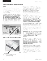
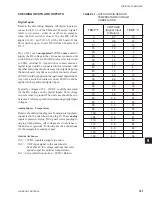
A 240-24 Volt Ratio Transformer (T3)
is used to derive nominal 12 volt output
from the 120 volt supply.
Summary of Contents for YCAL0019
Page 55: ...FORM 150 67 NM2 209 55 JOHNSON CONTROLS 5 5 ELEMENTARY WIRING DIAGRAM CON T LD12699D...
Page 57: ...FORM 150 67 NM2 209 57 JOHNSON CONTROLS 5 5 ELEMENTARY WIRING DIAGRAM CON T LD12693C...
Page 59: ...FORM 150 67 NM2 209 59 JOHNSON CONTROLS 5 5 ELEMENTARY WIRING DIAGRAM CON T LD 12198...
Page 61: ...FORM 150 67 NM2 209 61 JOHNSON CONTROLS 5 5 LD12702 ELEMENTARY WIRING DIAGRAM CON T...
Page 63: ...FORM 150 67 NM2 209 63 JOHNSON CONTROLS 5 5 LD12696 ELEMENTARY WIRING DIAGRAM CON T...
Page 65: ...FORM 150 67 NM2 209 65 JOHNSON CONTROLS 5 5 CONNECTION WIRING DIAGRAM CON T LD12703B...
Page 67: ...FORM 150 67 NM2 209 67 JOHNSON CONTROLS 5 5 CONNECTION WIRING DIAGRAM CON T LD12697B...

