JOHNSON CONTROLS
2
FORM 150.67-NM2 (209)
This equipment is a relatively complicated ap pa ra tus.
Dur ing installation, operation, maintenance or service,
in di vid u als may be exposed to certain com po nents or
conditions in clud ing, but not limited to: re frig er ants,
oils, materials un der pressure, rotating com po nents,
and both high and low voltage. Each of these items
has the po ten tial, if misused or handled im prop er ly, to
cause bodi ly injury or death. It is the obligation and
re spon si bil i ty of operating/service per son nel to iden ti fy
and rec og nize these inherent hazards, protect them selves,
and pro ceed safely in completing their tasks. Failure to
com ply with any of these requirements could re sult in
se ri ous dam age to the equipment and the prop er ty in
IMPORTANT!
READ BEFORE PROCEEDING!
GENERAL SAFETY GUIDELINES
which it is sit u at ed, as well as severe personal injury or
death to them selves and people at the site.
This document is intended for use by owner-authorized
operating/service personnel. It is expected that this
in di vid u al possesses independent training that will
en able them to perform their assigned tasks properly
and safe ly. It is essential that, prior to performing any
task on this equipment, this individual shall have read
and un der stood this document and any referenced
materials. This in di vid u al shall also be familiar with and
comply with all ap pli ca ble governmental standards and
regulations per tain ing to the task in question.
SAFETY SYMBOLS
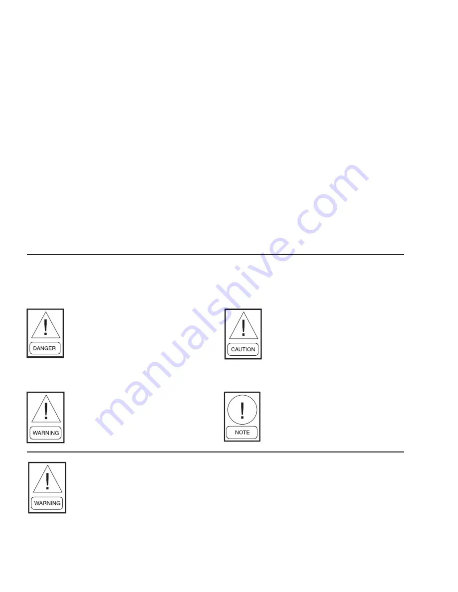
The following symbols are used in this document to alert the reader to areas of potential hazard:
CAUTION identifi es a hazard which
could lead to damage to the ma chine,
damage to other equip ment and/or
en vi ron men tal pollution. Usually an
in struc tion will be given, together with
a brief ex pla na tion.
NOTE is used to highlight ad di tion al
information which may be helpful to
you.
DANGER indicates an im mi nent ly
hazardous situation which, if not
avoid ed, will re sult in death or se ri ous
injury.
WARNING indicates a potentially
haz ard ous sit u a tion which, if not
avoid ed, could result in death or se-
ri ous in ju ry.
External wiring, unless specifi ed as an optional connection in the man u fac tur er’s prod uct
line, is NOT to be connected inside the micro pan el cab i net. De vic es such as re lays, switch es,
transducers and controls may NOT be installed inside the pan el. NO external wiring is al-
lowed to be run through the micro panel. All wir ing must be in ac cor dance with YORK’s
pub lished spec i fi ca tions and must be per formed ONLY by qual i fi ed YORK personnel. YORK
will not be re spon si ble for dam ag es/problems re sult ing from im prop er con nec tions to the
con trols or ap pli ca tion of im prop er con trol sig nals. Failure to fol low this will void the
man u fac tur er’s warranty and cause serious dam age to property or injury to per sons.
Summary of Contents for YCAL0019
Page 55: ...FORM 150 67 NM2 209 55 JOHNSON CONTROLS 5 5 ELEMENTARY WIRING DIAGRAM CON T LD12699D...
Page 57: ...FORM 150 67 NM2 209 57 JOHNSON CONTROLS 5 5 ELEMENTARY WIRING DIAGRAM CON T LD12693C...
Page 59: ...FORM 150 67 NM2 209 59 JOHNSON CONTROLS 5 5 ELEMENTARY WIRING DIAGRAM CON T LD 12198...
Page 61: ...FORM 150 67 NM2 209 61 JOHNSON CONTROLS 5 5 LD12702 ELEMENTARY WIRING DIAGRAM CON T...
Page 63: ...FORM 150 67 NM2 209 63 JOHNSON CONTROLS 5 5 LD12696 ELEMENTARY WIRING DIAGRAM CON T...
Page 65: ...FORM 150 67 NM2 209 65 JOHNSON CONTROLS 5 5 CONNECTION WIRING DIAGRAM CON T LD12703B...
Page 67: ...FORM 150 67 NM2 209 67 JOHNSON CONTROLS 5 5 CONNECTION WIRING DIAGRAM CON T LD12697B...


