background image

FORM 150.67-NM2 (209)

63

JOHNSON CONTROLS

5

5

LD12696

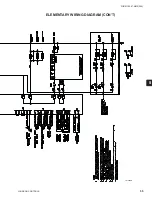
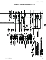
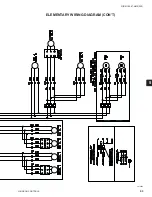
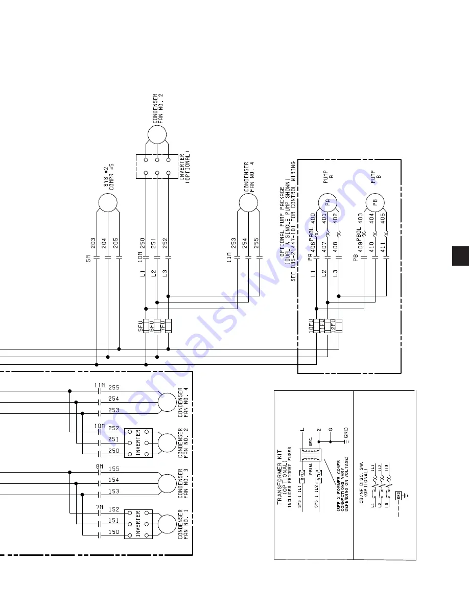
ELEMENTARY WIRING DIAGRAM (CON’T)

Summary of Contents for YCAL0019

Page 1: ...56 0066 AIR COOLED SCROLL CHILLERS STYLE E 50 Hz 15 65 TON INSTALLATION OPERATION MAINTENANCE AIR COOLED LIQUID CHILLERS HERMETIC SCROLL Supersedes 150 67 NM2 1007 Form 150 67 NM2 209 LD10950 R 410A 0...

Page 2: ...aterials This individual shall also be familiar with and comply with all applicable governmental standards and regulations pertaining to the task in question SAFETY SYMBOLS The following symbols are u...

Page 3: ...el to verify the applicability of these documents to the equipment in question If there is any question in the mind of operating service personnel as to the applicability of these documents then prior...

Page 4: ...hutdown 12 SECTION 2 PRODUCT DESCRIPTION 13 INTRODUCTION 13 GENERAL SYSTEM DESCRIPTION 13 Compressors 13 Evaporator Heat Exchanger 13 Condenser 14 MILLENIUM CONTROL CENTER 14 POWER PANEL 15 ACCESSORIE...

Page 5: ...eral Requirements 36 WIRING 36 Evaporator Pump Start Contacts 36 System Run Contacts 36 Alarm Status Contacts 37 Remote Start Stop Contacts 37 Remote Emergency Cutoff 37 Remote Temp Reset Input 37 Loa...

Page 6: ...OMMISSIONING 121 COMMISSIONING 121 PREPARATION POWER OFF 121 Inspection 121 Refrigerant Charge 121 Service and Oil Line Valves 121 Compressor Oil 121 Fans 121 Isolation Protection 121 Control Panel 12...

Page 7: ...135 Oper Data Key 135 Oper Data Quick Reference List 138 Print Key 139 Operating Data Printout 139 History Printout 140 History Displays 140 Software Version 142 ENTRY KEYS 143 Up and Down Arrow Keys...

Page 8: ...CONDENSER FAN CONTROL 161 YCAL0019 0028 LOW AMBIENT FAN CONTROL OPTION 165 General 165 Potentiometer Configuration 165 Wiring 166 Programming 167 YCAL0033 LOW AMBIENT FAN CONTROL OPTION 168 General 1...

Page 9: ...189 Oil Level check 189 Oil Analysis 189 CONDENSER FAN MOTORS 189 CONDENSER COILS 189 OPERATING PARAMETERS 189 ON BOARD BATTERY BACK UP 189 PLATE AND FRAME HEAT EXCHANGER EVAPORATOR HEATER 189 OVERAL...

Page 10: ...the designed parameters specified All warranty claims must specify the unit model serial number order number and run hours starts Model and serial number information is printed on the unit identificat...

Page 11: ...ocument supplied with the unit are the property of YORK which reserves all rights They may not be reproduced in whole or in part without prior written authorization from an authorized YORK representat...

Page 12: ...rotating fans Sharp Edges The fins on the air cooled condenser coils have sharp metal edges Reasonable care should be taken when working in contact with the coils to avoid the risk of minor abrasions...

Page 13: ...oil from incidental damage and restrict unauthorized access to internal components Units are designed in accordance with NFPA 70 National Electric Code ASHRAE ANSI 15 Safety code for mechanical refrig...

Page 14: ...e current protected They feature ball bearings that are double sealed and permanently lubricated MILLENIUM CONTROL CENTER All controls are contained in a NEMA 3R 12 and equivalent to IP55 cabinet with...

Page 15: ...us Number of compressors running Liquid solenoid valve status Load unload timer status Water pump status Provisions are included for pumpdown at shutdown optional remote chilled water temperature rese...

Page 16: ...exceed five mph it is recommended that Optional Condenser Louvered Enclosure Panels also be included Factory Mounted AMBIENT KIT HIGH Required if units are to operate when the ambient temperature is a...

Page 17: ...ove mentioned flow switch Pretempco model DPS300AP40PF 82582 5 300 psi max working pressure SPDT 5 amp 125 250VAC switch Range 0 40 PSID deadband 0 5 0 8 psi with 1 4 NPTE Pressure Connections CONDENS...

Page 18: ...ber of 5 8 15mm thickness one layer of anti vibrating heavy material thickness of 1 8 3mm Both are closed by two sheets of welded PVC reinforced for temperature and UV resistance Factory Mounted ULTRA...

Page 19: ...FORM 150 67 NM2 209 19 JOHNSON CONTROLS 2 COMPRESSORS FAN ASSEMBLIES CONDENSER COILS CONTROL POWER PANEL HEAT EXCHANGER FIG 1 UNIT COMPONENTS SINGLE SYSTEM UNITS UNIT COMPONENTS YCAL0019 0033...

Page 20: ...0 67 NM2 209 Product Description LD11463 KEYPAD DISPLAY UNIT SWITCH COMPRESSOR CONTACTORS USER TERMINAL BLOCK CIRCUIT BREAKER FIG 2 CONTROL POWER PANEL COMPONENTS SINGLE SYSTEM UNITS CONTROL POWER PAN...

Page 21: ...FORM 150 67 NM2 209 21 JOHNSON CONTROLS 2 HEAT EXCHANGER CONDENSER COILS LD12477 COMPRESSORS CONTROL POWER PANEL FAN ASSEMBLIES FIG 3 UNIT COMPONENTS DUAL SYSTEM UNITS UNIT COMPONENTS YCAL0043 0066...

Page 22: ...S 22 FORM 150 67 NM2 209 Product Description LD11458a FIG 4 CONTROL POWER PANEL COMPONENTS DUAL SYSTEM UNITS TERMINAL BLOCK FAN FUSES CR1 CR2 COMPRESSOR CONTACTS TB1 CTB1 CONTROL POWER PANEL COMPONENT...

Page 23: ...sd Single Point Non Fused Disconnect bx Single Point Circuit Breaker qq Special Power Option Required trans Cntrl Transformer PIN 18 x No Control Transformer Required t Control Transformer Required q...

Page 24: ...X No Option Required Q Special Quote PUMP PIN 26 X No Motor Current C Motor Current Readout Q Special Quote REMOTE Remote Panel PIN 27 X No Remote Panel Required O OptiView Remote Panel Required Q Spe...

Page 25: ...al Flanges Required FLOW Flow Switch PIN 41 X No Flow Switch Required S One Flow Switch Required T Two Flow Switches Required U Three Flow Switches Required D One Differential Pressure Switch Required...

Page 26: ...Required Q Special Quote ISOL Vibration Isolators PIN 54 X No Isolators Required 1 1 Deflection Isolators Required N Neoprene Isolators Required S Seismic Isolators Required Q Special Isolators Requir...

Page 27: ...r 2 5 en tire unit Q Special Warranty REFWTY Refrigerant Warranty PIN 56 X No Refrigerant Warranty Required 1 1 Year Refrigerant 2 2 Year Refrigerant 5 5 Year Refrigerant SHIP Ship Instructions PIN 57...

Page 28: ...8 FORM 150 67 NM2 209 Product Description LD11417 FIG 5 REFRIGERANT FLOW DIAGRAM OPTIONAL AIR COOLED CONDENSERS OPTIONAL DISCHARGE LINE BALL VALVE HOT DISCHARGE GAS LINE OPTIONAL SERVICE VALVE REFRIGE...

Page 29: ...to ensure that all components have been delivered and that no damage has occurred during transit If any damage is evident it should be noted on the carrier s freight bill and a claim entered in accor...

Page 30: ...t dataplate for unit weight When using lifting cables a spreader bar or frame should be used in order to prevent damage to the unit from the lifting chains Units are provided with lifting eyes in the...

Page 31: ...iller and on the shipping bag Forks must extend beyond the width of the unit for proper lift The thick ness of the fork blade must be smaller then the opening of the lifting hole Improper fork positio...

Page 32: ...ting chains hitting the chiller Never lift the chiller using a forklift or by hooking to the top rails Use only the lifting holes provided Lifting Instructions are placed on a label on the chiller and...

Page 33: ...s completely assembled units containing full operating charge and care should be taken to avoid damage due to rough handling SECTION 4 INSTALLATION INSPECTION Immediately upon receiving the unit it sh...

Page 34: ...fan operation Considerations should be made utilizing noise levels published in the YORK Engineering Guide for the specific chiller model Sound blankets for the compressors and low sound fans are ava...

Page 35: ...aterial into or through the cooler 5 As an aid to servicing thermometers and pressure gauges should be installed in the inlet and outlet water lines 6 The chilled water lines that are exposed to outdo...

Page 36: ...acity and maximum dual element fuse size are given in Tables 6 Copper power wiring only should be used for supplying power to the chiller This is recommended to avoid safety and reliability issues res...

Page 37: ...2 and 4 and unit wiring diagram Load Limit Input Load limiting is a feature that prevents the unit from loading beyond a desired value The unit can be load limited either 33 40 50 66 or 80 depending...

Page 38: ...er from the unit at or below freezing temperatures can result in damage to the evaporator and unit as a result of the chilled liquid freezing LD07719 Power Panel Control Panel Terminal Block NF Discon...

Page 39: ...of power can be supplying the unit power panel To prevent serious injury or death the technician should verify that NO LETHAL VOLTAGES are present inside the panel AFTER disconnecting power PRIOR to...

Page 40: ...e for application guidelines 3 The evaporator is protected against freezing to 20 F 28 8 C with an electric heater as standard 4 For operation at temperatures below 25 F 3 9 C the optional Low Ambient...

Page 41: ...ressure Drop Curves may extend past the minimum and maximum water flow ranges LD14085 YCAL0019 0033 HEAT EXCHANGER FLOW GPM YCAL COOLER CURVE 0019 A 0022 B 0028 D 0033 C ENGLISH 0 1 1 0 10 0 100 0 100...

Page 42: ...ENGLISH 1 10 100 10 100 1000 FLOW GPM Press Drop Ft H 2 O A B C YCAL COOLER CURVE 0043 A 0046 B 0052 B 0056 C 0066 C Note Water Pressure Drop Curves may extend past the minimum and maximum water flow...

Page 43: ...2 For leaving water temperature higher than 55 F 12 8 C contact the nearest YORK Office for application guidelines 3 The evaporator is protected against freezing to 20 F 28 8 C with an electric heate...

Page 44: ...ITATIONS SI Note Water Pressure Drop Curves may extend past the minimum and maximum water flow ranges LD14086 YCAL0019 0033 HEAT EXCHANGER FLOW GPM YCAL COOLER CURVE 0019 A 0022 B 0028 D 0033 C SI 0 1...

Page 45: ...00 1 10 100 FLOW L S Press Drop kPA B A C OPERATIONAL LIMITATIONS SI Note Water Pressure Drop Curves may extend past the minimum and maximum water flow ranges LD12452 YCAL0043 0066 HEAT EXCHANGER FLOW...

Page 46: ...Comp 1 Comp 2 Comp 3 Comp 4 Comp 5 Comp 6 0019 109 79 44 70 46 06 12 3 1 25 1 8 1454 1597 1481 1624 7 7 0022 109 79 44 70 46 06 15 1 1 30 1 8 1567 1781 1597 1811 8 8 0028 3012 1135 1270 20 0 1 0 20 4...

Page 47: ...ec tions Size Inches Ckt 1 Ckt 2 Ckt 1 Ckt 2 Ckt 1 Ckt 2 0019 34 7 2 X 17 2 X 0 3 920 10833 2 X N A N A N A 1 2 300 450 10 150 2 0022 34 7 3 X 17 2 X 0 3 920 10833 2 X N A N A N A 1 6 300 450 10 150 2...

Page 48: ...e Frequency Low Noise Fan with compressor sound blankets 63 125 250 500 1000 2000 4000 8000 dBA YCAL0019 80 79 79 74 72 69 63 64 77 YCAL0022 82 80 80 75 73 69 63 63 78 YCAL0028 89 84 88 85 80 76 71 68...

Page 49: ...88 86 82 77 73 69 87 YCAL0046 88 87 88 86 82 77 73 69 87 YCAL0052 97 94 95 93 89 84 80 76 94 YCAL0056 98 95 96 93 89 84 80 76 94 YCAL0066 90 91 91 89 85 80 77 72 90 50Hz Line Frequency Ultra Quiet Fan...

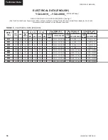
Page 50: ...NGE LUGS PHASE LUG WIRE RANGE LUGS PHASE LUG WIRE RANGE 0019 400 45 60 50 60 50 60 1 14 AWG 2 0 PB 0800 1 14 AWG 1 0 1 14 AWG 1 0 0022 400 48 60 60 60 60 60 1 14 AWG 2 0 PB 0800 1 14 AWG 1 0 1 14 AWG...

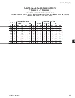
Page 51: ...PRESSOR FAN SYSTEM 2 COMPRESSOR FAN COMPR 1 COMPR 2 FANS COMPR 1 COMPR 2 FANS RLA LRA RLA LRA QTY FLA RLA RLA LRA RLA LRA QTY FLA RLA 18 6 114 18 6 114 2 1 3 2 5 20 0 125 20 0 125 2 1 3 2 5 21 8 140 2...

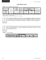
Page 52: ...at or below freezing temperatures can result in damage to the evaporator and unit as a result of the chilled liquid freezing ELECTRICAL DATA TABLE 7 MICRO PANEL POWER SUPPLY VOLTAGE RANGE VOLTAGE COD...

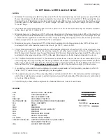
Page 53: ...motor plus 100 of the rated load amps for all other loads included in the circuit Otherwise an HACR type circuit breakers must be used Maximum HACR circuit breaker rating is based on 225 of the rated...

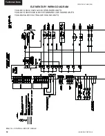
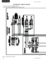
Page 54: ...54 FORM 150 67 NM2 209 Technical Data ELEMENTARY WIRING DIAGRAM FIG 10 CONTROL CIRCUIT SINGLE YCAL0019 0022 0028 0033 STANDARD UNITS YCAL0019 0022 0028 0033 STANDARD LOW SOUND UNITS YCAL0028 0033 ULTR...

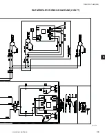
Page 55: ...FORM 150 67 NM2 209 55 JOHNSON CONTROLS 5 5 ELEMENTARY WIRING DIAGRAM CON T LD12699D...

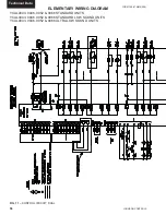
Page 56: ...ORM 150 67 NM2 209 Technical Data ELEMENTARY WIRING DIAGRAM FIG 11 CONTROL CIRCUIT DUAL YCAL0043 0046 0052 0066 STANDARD UNITS YCAL0043 0046 0052 0066 STANDARD LOW SOUND UNITS YCAL0043 0046 0052 0066...

Page 57: ...FORM 150 67 NM2 209 57 JOHNSON CONTROLS 5 5 ELEMENTARY WIRING DIAGRAM CON T LD12693C...

Page 58: ...JOHNSON CONTROLS 58 FORM 150 67 NM2 209 Technical Data FIG 12 POWER CIRCUIT SINGLE YCAL 0019 0022 STANDARD UNITS YCAL 0019 0022 STANDARD LOW SOUND UNITS ELEMENTARY WIRING DIAGRAM LD 12197...

Page 59: ...FORM 150 67 NM2 209 59 JOHNSON CONTROLS 5 5 ELEMENTARY WIRING DIAGRAM CON T LD 12198...

Page 60: ...50 67 NM2 209 Technical Data LD12701 FIG 13 POWER CIRCUIT SINGLE STYLE D ELEMENTARY WIRING DIAGRAM YCAL 0019 0022 0028 0033 STANDARD UNITS YCAL 0019 0022 0028 0033 STANDARD LOW SOUND UNITS YCAL 0028 0...

Page 61: ...FORM 150 67 NM2 209 61 JOHNSON CONTROLS 5 5 LD12702 ELEMENTARY WIRING DIAGRAM CON T...

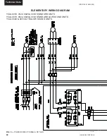
Page 62: ...209 Technical Data YCAL0043 0046 0052 0056 0066 STANDARD UNITS YCAL0043 0046 0052 0056 0066STANDARD LOW SOUND UNITS YCAL0043 0046 0052 0056 0066 ULTRA LOW SOUND UNITS ELEMENTARY WIRING DIAGRAM LD12695...

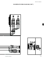
Page 63: ...FORM 150 67 NM2 209 63 JOHNSON CONTROLS 5 5 LD12696 ELEMENTARY WIRING DIAGRAM CON T...

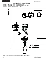
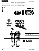
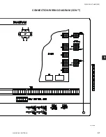
Page 64: ...NM2 209 Technical Data CONNECTION WIRING DIAGRAM FIG 14 CONNECTION WIRING DIAGRAM MICROBOARD SINGLE CIRCUIT YCAL0019 0022 0028 0033 STANDARD UNITS YCAL0019 0022 0028 0033 STANDARD LOW SOUND UNITS YCAL...

Page 65: ...FORM 150 67 NM2 209 65 JOHNSON CONTROLS 5 5 CONNECTION WIRING DIAGRAM CON T LD12703B...

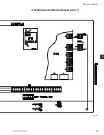
Page 66: ...nical Data FIG 14A CONNECTION WIRING DIAGRAM MICROBOARD DUAL CIRCUIT CONNECTION WIRING DIAGRAM YCAL0043 0046 0052 0056 0066 STANDARD UNITS YCAL0043 0046 0052 0056 0066 STANDARD LOW SOUND UNITS YCAL004...

Page 67: ...FORM 150 67 NM2 209 67 JOHNSON CONTROLS 5 5 CONNECTION WIRING DIAGRAM CON T LD12697B...

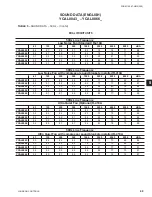
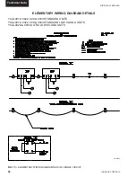
Page 68: ...9 Technical Data FIG 15 ELEMENTARY WIRING DIAGRAM DETAILS SINGLE CIRCUIT ELEMENTARY WIRING DIAGRAM DETAILS YCAL0019 0022 028 0033 STANDARD UNITS YCAL0019 0022 028 0033 STANDARD LOW SOUND UNITS YCAL002...

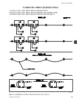
Page 69: ...FIG 16 ELEMENTARY WIRING DIAGRAM DETAILS DUAL CIRCUIT ELEMENTARY WIRING DIAGRAM DETAILS LD12689 YCAL0043 0046 0052 0056 0066 STANDARD UNITS YCAL0043 0046 0052 0056 0066 STANDARD LOW SOUND UNITS YCAL00...

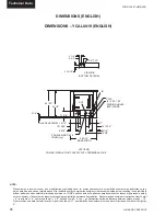
Page 70: ...r must consider potential performance degradation Recommended minimum clearances front to wall 6 rear to wall 6 cooler end to wall 4 0 coil end to wall 6 top no obstructions allowed distance between a...

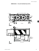
Page 71: ...TING HOLES typ COMPR END 1 1 16 5 17 2 1 4 ORIGIN Y C G X 44 3 8 32 1 8 6 1 8 1 1 16 CONTROL PANEL END END CAP WIDTH FRONT VIEW 109 3 16 RIGGING HOLES 2 3 0 X 1 50 BOTH SIDES 15 5 8 44 1 2 74 1 2 97 1...

Page 72: ...ty cutouts however the system designer must consider potential performance degradation Recommended minimum clearances front to wall 6 rear to wall 6 cooler end to wall 4 0 coil end to wall 6 top no ob...

Page 73: ...TING HOLES typ COMPR END 1 1 16 5 17 2 1 4 ORIGIN Y C G X 44 3 8 32 1 8 6 1 8 1 1 16 CONTROL PANEL END END CAP WIDTH FRONT VIEW 109 3 16 RIGGING HOLES 2 3 0 X 1 50 BOTH SIDES 15 5 8 44 1 2 74 1 2 97 1...

Page 74: ...culation ensures rated performance reli able operation and ease of maintenance Site restrictions may compromise minimum clearances indicated below resulting in unpredictable airflow patterns and possi...

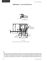
Page 75: ...5 1 16 6 1 8 1 1 1 16 1 1 16 5 17 CONTROL PANEL CONTROL PANEL END COMPR END ORIGIN Y C G X END CAP WIDTH 118 5 16 RIGGING HOLES 2 7 0 X 2 25 FORKLIFT HOLES BOTH SIDES 2 3 0 X 1 50 BOTH SIDES 1 7 8 R 4...

Page 76: ...esigner must consider potential performance degradation Recommended minimum clearances front to wall 6 rear to wall 6 cooler end to wall 4 0 coil end to wall 6 top no obstructions allowed distance bet...

Page 77: ...2 1 8 9 44 3 8 32 1 8 15 5 8 50 1 2 80 1 2 105 1 16 6 1 8 1 1 1 16 1 1 16 5 17 FRONT VIEW TOP VIEW 9 16 DIA MOUNTING HOLES typ CONTROL PANEL CONTROL PANEL END COMPR END ORIGIN Y C G X C G X Z END CAP...

Page 78: ...ance high pressure safety cutouts however the system designer must consider potential performance degradation Recommended minimum clearances front to wall 6 rear to wall 6 cooler end to wall 4 0 coil...

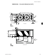
Page 79: ...GLISH CON T 90 9 16 45 5 16 Y C G X 1 1 16 ORIGIN END CAP WIDTH 21 13 16 TOP VIEW 9 13 16 1 1 1 9 13 9 16 DIA MOUNTING HOLES typ 144 13 16 15 1 16 13 15 16 TWO LIFTING HOLES BOTH SIDES FRONT VIEW C G...

Page 80: ...ance high pressure safety cutouts however the system designer must consider potential performance degradation Recommended minimum clearances front to wall 6 rear to wall 6 cooler end to wall 4 0 coil...

Page 81: ...LISH CON T 90 9 16 45 5 16 Y C G X 1 1 16 ORIGIN END CAP WIDTH 20 1 16 TOP VIEW 9 13 16 1 1 16 9 13 16 9 16 DIA MOUNTING HOLES typ 144 13 16 15 1 16 13 15 16 TWO LIFTING HOLES BOTH SIDES FRONT VIEW C...

Page 82: ...f maintenance Site restrictions may compromise minimum clearances indicated below resulting in unpredictable airflow patterns and possible diminished performance YORK s unit controls will optimize ope...

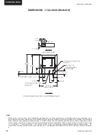
Page 83: ...1 16 TOP VIEW 1 1 16 CONTROL PANEL Y C G X 1 1 16 ORIGIN END CAP WIDTH 9 13 16 713 9 13 16 873 623 5 8 DIA MOUNTING HOLES TYP 144 13 16 15 1 16 13 15 16 TWO LIFTING HOLES BOTH SIDES FRONT VIEW 38 5 5...

Page 84: ...f maintenance Site restrictions may compromise minimum clearances indicated below resulting in unpredictable airflow patterns and possible diminished performance YORK s unit controls will optimize ope...

Page 85: ...144 13 16 15 1 16 14 25 3 8 28 9 16 CONTROL PANEL TWO LIFTING HOLES BOTH SIDES Y TOP VIEW FRONT VIEW 1 1 16 1 1 16 889 625 715 1 015 ORIGIN 9 13 16 9 13 16 B B 5 8 DIA MOUNTING HOLES TYP END CAP WIDT...

Page 86: ...imize operation without nuisance high pressure safety cutouts however the system designer must consider potential performance degradation Recommended minimum clearances front to wall 6 rear to wall 6...

Page 87: ...NGLISH CON T 90 9 16 43 5 16 16 11 16 38 5 3 16 153 5 8 15 1 16 16 25 3 8 28 9 16 CONTROL PANEL TWO LIFTING HOLES BOTH SIDES Y TOP VIEW C C G X FRONT VIEW C G X Z 1 1 16 1 1 16 ORIGIN 9 13 16 9 13 16...

Page 88: ...t consider potential performance degradation Recommended minimum clearances front to wall 2m rear to wall 2m cooler end to wall 1 2m coil end to wall 2m top no obstructions allowed distance between ad...

Page 89: ...TOP VIEW 14 DIA MOUNTING HOLES typ COMPR END 28 126 431 58 ORIGIN Y C G X 1128 815 156 28 CONTROL PANEL END END CAP WIDTH FRONT VIEW 2774 RIGGING HOLES 2 76 X 38 BOTH SIDES 398 1130 1892 2466 2 178 X...

Page 90: ...signer must consider potential performance degradation Recommended minimum clearances front to wall 2m rear to wall 2m cooler end to wall 1 2m coil end to wall 2m top no obstructions allowed distance...

Page 91: ...W 14 DIA MOUNTING HOLES typ COMPR END 28 126 431 58 ORIGIN Y C G X 1128 815 156 28 CONTROL PANEL END END CAP WIDTH FRONT VIEW 2774 RIGGING HOLES 2 76 X 38 BOTH SIDES 398 1130 1892 2466 2 178 X 57 FORK...

Page 92: ...t consider potential performance degradation Recommended minimum clearances front to wall 2m rear to wall 2m cooler end to wall 1 2m coil end to wall 2m top no obstructions allowed distance between ad...

Page 93: ...070 229 1128 815 398 1282 2044 2669 156 25 28 28 126 431 CONTROL PANEL COMPR END ORIGIN Y C G X END CAP WIDTH 3005 RIGGING HOLES 2 178 X 57 FORKLIFT HOLES BOTH SIDES 2 76 X 38 BOTH SIDES 47 R 410A CHI...

Page 94: ...gner must consider potential performance degradation Recommended minimum clearances front to wall 2m rear to wall 2m cooler end to wall 1 2m coil end to wall 2m top no obstructions allowed distance be...

Page 95: ...58 86 450 1070 229 1128 815 398 1282 2044 2669 156 25 28 28 126 431 FRONT VIEW TOP VIEW 14 DIA MOUNTING HOLES typ CONTROL PANEL CONTROL PANEL END COMPR END ORIGIN Y C G X C G X Z END CAP WIDTH 3005 RI...

Page 96: ...ressure safety cutouts however the system designer must consider potential performance degradation Recommended minimum clearances front to wall 2m rear to wall 2m cooler end to wall 1 2m coil end to w...

Page 97: ...5 5 DIMENSIONS YCAL0043 SI CON T 2301 1150 Y C G X 28 END CAP WIDTH ORIGIN 554 TOP VIEW 249 28 249 14 DIA MOUNTING HOLES typ 3678 383 355 TWO LIFTING HOLES BOTH SIDES FRONT VIEW C G X Z 965 135 645 34...

Page 98: ...ressure safety cutouts however the system designer must consider potential performance degradation Recommended minimum clearances front to wall 2m rear to wall 2m cooler end to wall 1 2m coil end to w...

Page 99: ...5 5 DIMENSIONS YCAL0046 SI CON T 2301 1150 Y C G X 28 ORIGIN END CAP WIDTH 509 TOP VIEW 249 28 249 14 DIA MOUNTING HOLES typ 3678 383 355 TWO LIFTING HOLES BOTH SIDES FRONT VIEW C G X Z 965 135 645 34...

Page 100: ...minimum clearances indicated below resulting in unpredictable airflow patterns and possible diminished performance YORK s unit controls will optimize operation without nuisance high pressure safety c...

Page 101: ...50 R 410A CHILLER 509 TOP VIEW 28 CONTROL PANEL Y C G X 28 ORIGIN END CAP WIDTH 249 713 249 873 623 16 DIA MOUNTING HOLES TYP 3678 383 355 TWO LIFTING HOLES BOTH SIDES FRONT VIEW 965 135 645 346 B B C...

Page 102: ...minimum clearances indicated below resulting in unpredictable airflow patterns and possible diminished performance YORK s unit controls will optimize operation without nuisance high pressure safety c...

Page 103: ...1 468 965 131 3678 383 356 645 726 CONTROL PANEL TWO LIFTING HOLES BOTH SIDES Y TOP VIEW FRONT VIEW 28 28 889 625 715 1 015 ORIGIN 249 249 B B 16 DIA MOUNTING HOLES TYP END CAP WIDTH COIL END COOLER E...

Page 104: ...without nuisance high pressure safety cutouts however the system designer must consider potential performance degradation Recommended minimum clearances front to wall 2m rear to wall 2m cooler end to...

Page 105: ...5 5 DIMENSIONS YCAL0066 SI CON T 2301 1100 424 965 131 3902 383 406 645 726 CONTROL PANEL TWO LIFTING HOLES BOTH SIDES Y TOP VIEW C G X FRONT VIEW C G X Z 28 28 ORIGIN 249 249 B B 14 DIA MOUNTING HOL...

Page 106: ...ical Data TECHNICAL DATA CLEARANCES 1 3 m 2 m 2 m 2 m NOTES 1 No obstructions allowed above the unit 2 Only one adjacent wall may be higher than the unit 3 Adjacent units should be 10 feet 3 Meters ap...

Page 107: ...ecifically for each chiller based on the option selection The drawing and table will be similar to the ones shown below The drawing will show the isolator locations along with the weight in pounds and...

Page 108: ...LRS 2 C2 660 SLRS 2 C2 520 SLRS 2 C2 660 SLRS 2 C2 520 SLRS 2 C2 660 YCAL0028 1 Deflection CIP B 450 CIP B 1000 CIP B 450 CIP B 750 CIP B 750 CIP B 1000 CIP B 750 CIP B 1000 Neoprene ND C ND C ND C ND...

Page 109: ...hiller Packed with the isolators and also in the control panel information packet is a drawing and table specifically for each chiller based on the option selection The drawing and table will be simil...

Page 110: ...ACK CP1 1D 675 675 1 32 DK PURPLE CP1 1D 900 900 1 02 DK GREEN CP1 1D 1200 1200 0 9 GRAY CP1 1D 1360 1360 0 77 WHITE CP1 1D 1785N 1785 0 88 GRAY RED MODEL NUMBER RATED CAPACITY LBS RATED DEFLECTION IN...

Page 111: ...LING ALL ISOLATORBASES TO THE SAME ELEVATION 1 4 INCH MAXIMUM DIFFERENCE CAN BE TOLERATED 4 BOLT ORANCHORALLISOLATORS TO SUPPRTING STRUC TURE UTILIZING BASE SLOTTED HOLES C 5 PLACE EQUIPMENT ON TOP OF...

Page 112: ...50 0 5 70 MODEL NUMBER RATED CAPACITY LBS RATED DEFLEC TION IN DURO 5 RD3 Brown WR 250 0 5 40 RD3 Brick Red WR 525 0 5 50 RD3 Lime WR 750 0 5 60 RD3 Charcoal WR 1100 0 5 70 MODEL NUMBER RATED CAPACITY...

Page 113: ...LOOR HOUSEKEEPING PAD OR SUB BASE ENSURING THAT ALL ISOLATOR CENTERLINES MATCH THE EQUIPMENT MOUNTING HOLES THE VMC GROUP RECOMMENDS THAT THE ISOLATOR BASE A BE INSTALLED ON A LEVEL SURFACE SHIM OR GR...

Page 114: ...ID LOAD LBS COLOR CODE ALLOWABLE G RATING HORIZONTAL Y2RSI 2D 150 150 2 42 62 234 WHITE 34 7 Y2RSI 2D 320 320 2 29 140 490 YELLOW 16 3 Y2RSI 2D 460 460 2 30 200 688 GREEN 11 3 Y2RSI 2D 710 710 2 15 33...

Page 115: ...LED AND ARE TO BE POSITIONED IN ACCORDANCE WITH THE SUBMITTAL DRAWINGS OR AS OTHERWISE RECOMMENDED 3 SET ISOLATORS ON FLOOR HOUSEKEEPING PAD OR SUB BASE ENSURING THAT ALL ISOLATOR CENTERLINES MATCH TH...

Page 116: ...022 kg CIP C Red w Red 029 24583 012 2254 to 2936 lbs 1022 to 1332 kg CIP C Green w Red 029 24583 013 CIP X ONE INCH DEFLECTION SPRING ISOLATOR CROSS REFERENCE Illustration shows single spring CIP B o...

Page 117: ...he isolator To use the isolator as blocking for the equipment insert a 10mm 1 4 shim between the upper load plate and vertical uprights Lower the equipment on the blocking or shimmed isolators 5 Compl...

Page 118: ...Bolt Dia Steel Plate Top Bottom Neoprene covered to prevent corrosion L T H W D ENGLISH Size D H L T W BC CS MBD ND C 2 9 16 2 3 4 5 1 2 1 4 2 5 16 4 1 8 1 2 13 x 1 1 2 ND D 3 3 8 2 3 4 6 1 4 5 16 4 5...

Page 119: ...o 2058 lbs 679 to 933 kg SLRS 2 C2 Silver 029 24585 012 2058 to 2619 lbs 933 to 1188 kg SLRS 2 C2 Gray w red 029 24585 013 2619 to 3180 lbs 1188 to 1442 kg SLRS 2 C2 Silver w red 029 24585 014 Value i...

Page 120: ...justment bolt 8 turns on each mount 9 Take one additional complete turn on each adjustment bolt in sequence until the top plate lifts off of the lower restraining nuts Take no additional turns on that...

Page 121: ...m Compressor Oil To add oil to a circuit connect a YORK hand oil pump Part No 470 10654 000 to the 1 4 oil charging connection on the compressors with a length of clean hose or copper line but do not...

Page 122: ...air from the top of the cooler using the plugged air vent mounted on the top of the cooler body Flow rates and pressure drops must be within the limits given in the Technical Data Section Operation ou...

Page 123: ...ree of foreign material wires metal chips etc 8 Visually inspect wiring power and control Wir ing MUST meet N E C and local codes 9 Check tightness of power wiring inside the power panel on both sides...

Page 124: ...0043 YCAL0066 units only Turn sys tem 1 OFF and system 2 ON refer to Option 2 under UNIT KEYS section for more informa tion on system switches Place the Unit Switch in the control panel to the ON posi...

Page 125: ...rom the heat exchanger Superheat should typically be set for no less than 10 Fwith only a single compressor running on a circuit The superheat is calculated as the difference between the actual temper...

Page 126: ...wn 4 Several seconds after the compressor starts that systems first condenser fan will be cycled on out door air temperature 25 F 4 C or discharge pressure See the section on Operating Controls for de...

Page 127: ...ware The IPU II board contains a coldfire microprocessor and is the controller and decision maker in the control panel The I O board handles all of the chiller I O Inputs and Outputs System inputs fro...

Page 128: ...until another key is pressed The system parameters can be scrolled with the use of the UP and DOWN arrow keys The display will update all information at a rate of about 1 a second Display Messages may...

Page 129: ...s message informs the operator that the UNIT switch on the control panel is in the OFF position which will not allow the unit to run The REMOTE CONTROLLED SHUTDOWN message indicates that either an ISN...

Page 130: ...programmed discharge pressure cutout This will only happen if the system is fully loaded and will shut only one compressor off If the system is not fully loaded discharge limiting will not go into ef...

Page 131: ...2 L O W S U C T P R E S S The PUMPING DOWN message indicates that a compressor in the respective system is presently in the process of pumping the system down When pumpdown is initiated on shutdown t...

Page 132: ...temperature sensor for the purpose of sensing internal scroll temperature This sensor protects the scrolls from overheating due to inadequate cooling that may occur when refrigerant charge is low or s...

Page 133: ...wn when the voltage exceeds the programmed trip voltage for 5 seconds The trip voltage is programmed at the factory according to compressor or unit RLA Restart will occur after the anti recycle timer...

Page 134: ...m X AC Timer System X Disch Limiting System X Suction Limiting System X Percentage Load Limiting Manual Overide Status System X Pumping Down on shutdown Unit Safeties Warning Messages System Safeties...

Page 135: ...nd DOWN arrow keys or the ENTER ADV key located under the ENTRY section DISPLAY PRINT KEYS With the UNITTYPE set as a liquid chiller no jumper to J11 12 the following list of operating data screens ar...

Page 136: ...G DEMAND indicates the current step in the capacity control scheme when in Return Water Control Mode The number of available steps are determined by how many compressors are in the unit In the above d...

Page 137: ...r is turned on When the temperature rises above 45 F the heater is turned off An under voltage condition will keep the heater off until full voltage is restored to the system The evaporator pump dry c...

Page 138: ...r Data Quick Reference List The following table is a quick reference list for information available under the OPER DATA key TABLE 11 OPERATION DATA Block of information repeats for each system LD12585...

Page 139: ...ATION TIME 3MIN BIVALENT HEAT DELAY TIME 30 MIN REMOTE UNIT ID PROGRAMMED 2 YORK HYDRO KIT PUMPS 1 410a PUMP TOTAL RUN HOURS XXXXX 410a OHNS NS SON S N C N CON C NT N RO T OL O S S UNIT DATA RETURN LI...

Page 140: ...built into the circuit board or manual resetting of a fault lock out When the HISTORY key is pressed a printout is transmitted of all system operating conditions which were stored at the instant the...

Page 141: ...essure Displays whether Manual Override was Enabled or Disabled Displays type of Current Feedback utilized Displays whether the optional European Soft Start was installed and selected Displays the pro...

Page 142: ...y will be the first display prior to the SYS 1 info If the micro is programmed for CURRENT FEEDBACK NONE no current display will appear Displays for System 1 starting with SYS X NUMBER OF COMPS RUNNIN...

Page 143: ...rrow key are also used for programming the control panel such as changing numerical or text values when programming cooling setpoints setting the daily schedule changing safety setpoints chiller optio...

Page 144: ...eaving Chilled Liquid Control The above message shows the current chilled water temperature SETPOINT at 45 0 F notice the cursor po sitioned under the number 0 Pressing either the UP or DOWN arrow wil...

Page 145: ...of 43 47 F Return Chilled Liquid Control In return chilled liquid control the range no longer has a X X F but only a X X F RANGE setpoint This indicates that the setpoint is not centered within the R...

Page 146: ...arrow and ENTER ADV keys After SUN Sunday schedule appears on the display a subsequent press of the SCHEDULE ADVANCE DAY key will display the Holiday schedule This is a two part display The first read...

Page 147: ...select the chiller outside ambient temperature cutout point If the ambient falls below this point the chiller will shut down Restart can occur when temperature rises 2 F 1 11 C above the cutout setpoi...

Page 148: ...ed differential pressure value that is used to stage the condenserfansoff inrelationtodischargepressure Refer to Condenser Fan Control in the UNIT OPERATION section and Tables 19 20 21 and 22 TheTOTAL...

Page 149: ...RESSURE CUTOUT WATER COOLING 80 0 PSIG 120 0 PSIG 80 0 PSIG 5 52 BARG 8 27 BARG 5 52 BARG GLYCOL COOLING 42 0 PSIG 70 0 PSIG 44 0 PSIG 2 9 BARG 4 83 BARG 3 03 BARG LOW AMBIENT TEMP CUTOUT STANDARD AMB...

Page 150: ...ntrol Pressure Display Only Holiday Cutout Schedule Chilled Liquid Suction Setpoint Pressure Cutout Range Remote Setpoint Low Ambient Temp Cutout Range Display Only Leaving Liquid EMS PWM Temperature...

Page 151: ...keys are then used to change that particular option After the option is changed the ENTER ADV key must be pressed to enter the data into memory Many of the OPTIONS displayed are only programmable unde...

Page 152: ...A L R E M O T E M O D E R E M O T E A M B I E N T C O N T R O L L O W A M B I E N T L O C A L R E M O T E M O D E L L O C A L C O N T R O L M O D E R E T U R N L I Q U I D C O N T R O L M O D E L E A...

Page 153: ...f the daily schedule that is programmed MANUAL OVERRIDE MODE DISABLED indicates that override mode has no effect or Manual Override Mode is enabled This is a service function and when enabled will all...

Page 154: ...ted The keypad and display will not respond during the update DO NOT reset or power down the chiller until the update is completed After the update is completed an automatic reboot will occur If an er...

Page 155: ...ORK HYDRO KIT PUMPS 2 are selected under Option 19 Presently this option should not be used CLOCK The CLOCK display shows the current day time and date Pressing the CLOCK key will show the current day...

Page 156: ...its English or Metric System Lead Lag Control Manual or Automatic Fan Control Mode Manual Override Mode Current Feedback Option Soft Start Option Unit Type Chiller MUST be Selected Via No Jumper Insta...

Page 157: ...within the control cooling range The Setpoint High Limit is the Setpoint plus the Cooling Range The Setpoint Low Limit is the Setpoint minus the Cooling Range Fig 18 should be utilized to aid in unde...

Page 158: ...on average run hours of the compressors in each system Manual Lead Lag selects specifically the sequence which the micro starts systems On a hot water start once a system starts it will turn on all co...

Page 159: ...nge Setpoint of 10 F 5 56 C Using the formulas in Table 20 the control range will be split up into six seven including hot gas segments with the Control Range determining the separation between segmen...

Page 160: ...ecreased by 1 with the wrap around This control scheme assures the same compressor does not repeatedly cycle on and off Notes 1 Step 1 is Hot Gas Bypass and is skipped when loading occurs Hot Gas Bypa...

Page 161: ...pump option is installed the active pump is selected by the selector switch EVAPORATOR HEATER CONTROL The evaporator heater is controlled by ambient air temperature When the ambient temperature drops...

Page 162: ...tage is decreased 20 PSIG and ramped back to the programmed off pressure minus the differential over the next 20 seconds A low ambient kit MUST be installed when AMBIENT CONTROL LOW AMBIENT is selecte...

Page 163: ...M TB7 9 TB7 10 1 3 FAN STAGE ON OFF CONTACTOR MICROBOARD OUTPUT FAN SYS 1 SYS 1 SYS 1 1 DP Fan Ctrl On Press DP Fan Ctrl On Press Diff Press 7M TB7 9 1 2 DP Fan Ctrl On Press and Fan Stage 1 is energi...

Page 164: ...10 1 3 2 4 FAN STAGE ON OFF CONTACTOR MICRO BOARD OUTPUT FAN SYS 1 SYS 2 SYS 1 SYS 2 SYS 1 SYS 2 1 DP Fan Ctrl On Press DP Fan Ctrl On Press Diff Press 7M 10M TB7 9 TB10 9 1 2 2 DP Fan Ctrl On Press...

Page 165: ...The VFD control signal is sent from a liquid temperature sensor connected to a condenser coil return bend The sensor is connected to S1 and COM terminals of the VFD in the control panel The sensor mus...

Page 166: ...single phase power in single phase power out and a 2 wire signal from the liquid line temperature sensor No start stop or other alternate power requirements are needed to operate the VFD Fig 25 shows...

Page 167: ...ol of the fans at reduced ambient temperatures assuring superheat and oil control is not compromised When the chiller and VFD fan control points are programmed properly the fans will operate as outlin...

Page 168: ...ltage power is applied to the VFD power inputs through the 7M contactor The chiller microprocessor will energize the 7M and 10M contactors whenever the system liquid line solenoid is energized The VFD...

Page 169: ...s is the range of pressure where the VSD modulates the fan speed from 0 RPM to full speed The range is subtracted from the setpoint to calculate the 0 RPM pressure Wiring VFD wiring is simple and requ...

Page 170: ...AN SYS 1 SYS 1 SYS 1 1 VFD Control 1 fan Variable Speed Fan Speed Is A Function Of Discharge Pressure When The Liquid Line Solenoid Is Energized Speed Increases With Pressure FAN Will Turn Off or Turn...

Page 171: ...FD turns the fan completely off or virtually off with a continued drop in pressure Single System VFD Enclosure Location LD12080 FIG 31 TYPICAL VFD ENCLOSURE LOCATIONS Dual System VFD Enclosure Locatio...

Page 172: ...onsite A quick check of the settings is recommended The jumpers must be in the positions shown in the following Table FIG 32 TYPICAL VFD ENCLOSURE CONFIGURATIONS Dual System VFD Enclosure SYS 2 SYS 1...

Page 173: ...e programmed for DISCHARGE PRESSURE CONTROL only This will assure condenser fan control of the chiller is solely by discharge pressure with no ambient control UnderthePROGRAMKey theFANCONTROLON PRESSU...

Page 174: ...02 FAN STAGE ON OFF CONTACTOR MICROBOARD FAN SYS 1 SYS 2 SYS 1 SYS 2 SYS 1 SYS 2 1 VFD Control 1 Fan Variable Speed Fan Speed Is A Function Of Discharge Pressure When The Liquid Line Solenoid Is Energ...

Page 175: ...he Load Limit input with a dry contact Load limiting is either 80 66 or 50 depending on the number of compressors on the unit Table 24 shows the load limiting permitted for the various number of compr...

Page 176: ...C Max Reset Value 20 F 11 11 C Input Signal 6VDC English Reset 6VDC x 20 F 12 F Reset 10 New Setpoint 45 F 12 F 57 F Metric Reset 6VDC x 11 11 C 6 67 C Reset 10 New Setpoint 7 22 C 6 67 C 13 89 C MaxR...

Page 177: ...buffers may be cleared by pressing the HIS TORY key and then repeatedly pressing the UP arrow key until you scroll past the last history buffer choice The following message will be displayed Pressing...

Page 178: ...UP and Down arrow keys but under normal circumstances would not be required or advised After the last start display the micro will display the first programmable value under the PROGRAM key SERVICE M...

Page 179: ...t J7 10 SYS 1 Suction Transducer or SYS 1 Low Pressure Switch J11 12 Unit Type Chiller NO Jumper J11 12 to 24 VDC YCUL Condensing Unit Jumper J11 12 to 24 VDC Do NOT Use J7 11 SYS 1 Discharge Pressure...

Page 180: ...JOHNSON CONTROLS 180 FORM 150 67 NM2 209 Service and Troubleshooting FIG 36 MICROBOARD LAYOUT TB5 TB1 TB6 TB7 TB8 TB9 TB10 J14 J13 J12 J15 J11 J10 J9 J8 J7 J6 J5 J3 I O BOARD IPU BOARD JP1 LD12721...

Page 181: ...ypically voltages of 24 36VDC could be measured for the DC voltage on the digital inputs This voltage is in reference to ground The unit case should be suf ficient as a reference point when measuring...

Page 182: ...o the microboard See Table 32 for voltage readings that correspond to specific liquid temperatures J6 1 drain shield connection 0VDC Return TABLE 32 ENTERING LEAVING CHILLED LIQUID TEMP SENSOR TEMPERA...

Page 183: ...put of the transducer All voltage reading are in reference to ground unit case V Pressure in PSIG x 01 5 or V Pressure in BARG x 145 5 where V dc voltage output Pressure pressure sensed by transducer...

Page 184: ...ge readings that correspond to specific suction pressures J7 9 5VDC return J7 11 drain shield connection 0VDC Digital Outputs Refer to the unit wiring diagram and Fig 37 The digital outputs are locate...

Page 185: ...0915576 The cable to connect the printer can either be locally assembled from the parts listed or ordered directly from WEIGH TRONIX under part number 287 040018 Parts The following parts are required...

Page 186: ...Defective IPU II I O Board 5 Replace IPU II I O Board or the Display Board or the Display Board Contact YORK Service before Replacingcircuit Boards FLOW SWITCH REM 1 No chilled liquid flow 1 Check ch...

Page 187: ...ward 2 Too much refrigerant 2 Remove refrigerant 3 Air in refrigerant system 3 Evacuate and recharge system 4 Defective discharge 4 Replace discharge pressure pressure transducer transducer Refer to S...

Page 188: ...START Installation Manual to aid in understanding compres sor operation and capacity control 2 Defective water temperature 2 Compare the display with a sensor thermometer Should be within 2 degrees R...

Page 189: ...gerant system down into a vacuum Doing so will cause internal arcing of the compressor motor which will result in failure of compressor CONDENSER FAN MOTORS Condenser fan motors are permanently lubric...

Page 190: ...cidence Timer P26 68 71 Analog SYS 2 Suction Temp EEV Only P27 72 75 Analog SYS 2 Run Time Seconds P28 76 79 Analog SYS 2 Suction Pressure P29 80 83 Analog SYS 2 Discharge Pressure P30 84 87 Analog P3...

Page 191: ...Remote P55 127 Digital P56 128 Coded SYS 1 Operational Code P57 129 Coded SYS 1 Fault Code P58 130 Coded SYS 2 Operational Code P59 131 Coded SYS 2 Fault Code P60 132 Coded ISN PAGE CHARACTER TYPE DA...

Page 192: ...HIGH OIL TEMPERATURE 12 MANUAL OVERRIDE 12 HIGH DISCHARGE TEMPERATE 13 SUCTION LIMITING 13 IMPROPER PHASE ROTATION 14 DISCHARGE LIMITING 14 LOW MOTOR CURRENT MP HPCO 15 CURRENT LIMITING 15 MOTOR CURRE...

Page 193: ...ODIFIER OFFSET XX P1 PROTOCOL XXXXXX P1 MANUAL MAC ADDRESS XXX P1 BAUD RATE XXXXX P1 PARITY XXXXX P1 STOP BITS X P2 PROTOCOL XXXXXXXXXX P2 MANUAL MAC ADDRESS XXX P2 BAUD RATE XXXXX P2 PARITY XXXXX P2...

Page 194: ...1 BAUD RATE 1200 76800 4800 1200 4800 9600 19200 38400 76800 AUTO SELECTABLE P2 BAUD RATE 1200 57600 1200 1200 4800 9600 19200 38400 57600 SELECTABLE P1 P2 MANUAL MAC ADDRESS 1 127 1 P1 P2 PARITY NONE...

Page 195: ...OO LONG 3 FLOATING POINT EXCEPTION 4 GET PACKET FAILED 5 GET TYPE FAILED 6 INVALID UNIT CONVERSION 7 INVALID HARDWARE SELECTION 8 REAL TIME FAULT 9 SPANISH TEXT TOO LONG 10 THREAD EXITED 11 THREAD FAI...

Page 196: ...INARY VALUE DESCRIPTION 1 START_STOP START STOP COMMAND 2 SS_SYS1 SYS 1 START STOP COMMAND SUCTION PRESSURE CONTROL 3 SS_SYS2 SYS 2 START STOP COMMAND SUCTION PRESSURE CONTROL SERIAL COMMUNICATION ANA...

Page 197: ...S2_DBG_CODE SYS 2 DEBUG CODE 32 S2_FAN_STAGE SYS 2 CONDENSER FAN STAGE 33 CONTROL_M0DE UNIT CONTROL MODE 1 LEAVING WATER 2 RETURN WATER 3 DISCHARGE AIR 4 SUCTION PRESS 5 COOLING 6 HEATING 34 AR_TIME A...

Page 198: ...RUN 7 S1_LLSV SYS 1 LIQUID LINE SOLENOID VALVE 8 S1_MODE_SV SYS 1 MODE SOLENOID VALVE HP ONLY 9 S1_HGBV SYS 1 HOT GAS BYPASS VALVE 10 S1_BHS BIVALENT HEAT SOURCE HP ONLY 11 S1_C2_RUN SYS 1 COMP 2 RUN...

Page 199: ...0 93 3 82 179 6 204 95 6 84 183 2 208 97 8 86 186 8 212 100 0 88 190 4 216 102 2 90 194 220 104 4 92 197 6 224 106 7 94 201 2 228 108 9 96 204 8 232 111 1 98 208 4 236 113 3 100 212 240 115 6 102 215...

Page 200: ...60 36 10 180 64 38 8 190 67 40 6 200 70 42 4 210 73 44 3 220 76 46 2 225 78 48 0 235 80 50 1 245 83 52 3 255 85 54 4 265 88 56 6 275 90 58 7 285 92 60 8 295 95 62 10 305 97 64 11 325 101 66 13 355 10...

Reviews: