background image

75

JOHNSON CONTROLS

SECTION 5 – TECHNICAL DATA

FORM 150.67-NM1 

ISSUE DATE: 4/28/2017

55

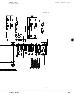
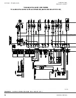
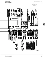
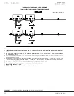
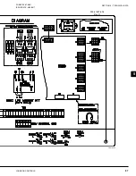
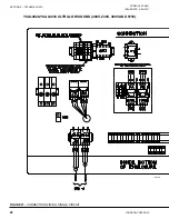
FIGURE 19 - 

POWER WIRING, SINGLE CIRCUIT

LD22082a

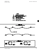
LD22082b

035-21487-105 

REV B

Summary of Contents for YCAL0019

Page 1: ...6 0066 AIR COOLED SCROLL CHILLERS STYLE E 60 HZ 15 65 TON Products are produced at a facility whose quality management systems are ISO9001 certified Issue Date April 28 2017 AIR COOLED LIQUID CHILLERS...

Page 2: ...this document and any referenced materials This in dividual shall also be familiar with and comply with all applicable industry and governmental standards and regulations pertaining to the task in que...

Page 3: ...product owner Updated manuals if applicable can be obtained by contacting the nearest Johnson Controls Service office or accessing the John son Controls QuickLIT website at http cgproducts johnsoncon...

Page 4: ...JOHNSON CONTROLS 4 FORM 150 67 NM1 ISSUE DATE 4 28 2017 THIS PAGE INTENTIONALLY LEFT BLANK...

Page 5: ...Shutdown 17 SECTION 2 PRODUCT DESCRIPTION 19 Introduction 19 General System Description 19 Compressors 19 Evaporator Heat Exchanger 19 Condenser 20 Coils 20 Low Sound Fans 20 Motors 20 Millennium Cont...

Page 6: ...ls Unit 24 Louvered Panels Full Unit 24 Sound Reduction Attenuation Options 24 Vibration Isolators 24 Unit Components YCAL0019 0033 25 Control Power Panel Components YCAL0019 0033 26 Unit Components Y...

Page 7: ...ions English 47 Voltage Limitations 47 Operational Limitations SI 50 Voltage Limitations 50 Physical Data English 53 Electrical Data English 54 Electrical Notes And Legend 59 General 133 Weight Distri...

Page 8: ...55 Fault Safety Status Messages 156 System Safeties 157 Unit Safeties 158 Unit Warning 158 Status Key Messages 160 DISPLAY PRINT KEYS 161 Oper Data Key 161 Oper Data Quick Reference List 164 Print Key...

Page 9: ...id Control 183 Leaving Chilled Liquid Control Override To Reduce Cycling 184 Leaving Chilled Liquid System Lead Lag And Compressor Sequencing 184 Return Chilled Liquid Control 185 Return Chilled Liqui...

Page 10: ...ystem 2 Suction Transducer 210 Digital Outputs 210 Parts 211 Assembly and Wiring 211 Obtaining a Printout 211 SECTION 10 MAINTENANCE 215 Important 215 Compressors 215 Oil Level Check 215 Oil Analysis...

Page 11: ...ingle Circuit 84 FIGURE 25 Connection Wiring Single Circuit 86 FIGURE 26 Connection Wiring Single Circuit 88 FIGURE 27 Connection Wiring Single Circuit 90 FIGURE 28 Connection Wiring Dual Circuit 93 F...

Page 12: ...ure Configurations 197 FIGURE 56 Inverter Power Wiring Sc 198 FIGURE 57 Potentiometer Settings 198 FIGURE 58 Inverter Wiring 199 FIGURE 59 Microboard Layout 206 FIGURE 60 I O Board Relay Contact Archi...

Page 13: ...rol Using Discharge Pressure 188 TABLE 21 YCAL0019 YCAL0033 Condenser Fan Control Using Discharge Pressure Only 188 TABLE 22 YCAL0043 YCAL0066 Condenser Fan Control Using Discharge Pressure 189 TABLE...

Page 14: ...JOHNSON CONTROLS 14 FORM 150 67 NM1 ISSUE DATE 4 28 2017 THIS PAGE INTENTIONALLY LEFT BLANK...

Page 15: ...signed parameters specified All warranty claims must specify the unit model serial number order number and run hours starts Model and serial number information is printed on the unit identi fication p...

Page 16: ...ual and any other document supplied with the unit are the property of Johnson Controls which reserves all rights They may not be reproduced in whole or in part without prior written authorization from...

Page 17: ...sk of injury from rotating fans Sharp Edges The fins on the air cooled condenser coils have sharp metal edges Reasonable care should be taken when working in contact with the coils to avoid the risk o...

Page 18: ...JOHNSON CONTROLS 18 FORM 150 67 NM1 ISSUE DATE 4 28 2017 SECTION 1 GENERAL CHILLER INFORMATION and SAFETY THIS PAGE INTENTIONALLY LEFT BLANK...

Page 19: ...dental damage and restrict unauthorized access to internal components Units are designed in accordance with NFPA 70 Na tional Electric Code ASHRAE ANSI 15 Safety code for mechanical refrigeration ASME...

Page 20: ...ors The fan motors are Totally EnclosedAir Over TEAO direct drive 6 pole current protected They feature ball bearings that are double sealed and permanently lubri cated MILLENNIUM CONTROL CENTER All c...

Page 21: ...essor Status of hot gas valves evaporator heater and fan operation Run permissive status Intensity of Protection European Standard International Electrotechnical Commission Number of compressors runni...

Page 22: ...power factors to a 0 90 0 95 Factory Mounted Control Options Ambient Kit Low Units will operate to 25 F 4 C This accessory includes all necessary components to permit chiller operation to 0 F 18 C Thi...

Page 23: ...unit and operating conditions by introducing an artificial load on the cooler Hot gas by pass is installed on only re frigerant system 1 on two circuited units Factory Mounted Heat Exchanger 300 PSIG...

Page 24: ...se of Louvered Panels described below Louvered Panels Full Unit Louvered panels surround the front back and sides of the unit They prevent unauthorized access and visu ally screen unit components Unre...

Page 25: ...ECTION 2 PRODUCT DESCRIPTION FORM 150 67 NM1 ISSUE DATE 4 28 2017 2 COMPRESSORS FAN ASSEMBLIES CONDENSER COILS CONTROL POWER PANEL HEAT EXCHANGER Figure 2 UNIT COMPONENTS SINGLE SYSTEM UNITS UNIT COMP...

Page 26: ...TE 4 28 2017 SECTION 2 PRODUCT DESCRIPTION LD11463 KEYPAD AND DISPLAY UNIT SWITCH COMPRESSOR CONTACTORS USER TERMINAL BLOCK CIRCUIT BREAKER Figure 3 CONTROL POWER PANEL COMPONENTS SINGLE SYSTEM UNITS...

Page 27: ...ION 2 PRODUCT DESCRIPTION FORM 150 67 NM1 ISSUE DATE 4 28 2017 2 HEAT EXCHANGER CONDENSER COILS LD12477 COMPRESSORS CONTROL POWER PANEL FAN ASSEMBLIES Figure 4 UNIT COMPONENTS DUAL SYSTEM UNITS UNIT C...

Page 28: ...7 NM1 ISSUE DATE 4 28 2017 SECTION 2 PRODUCT DESCRIPTION LD11458a Figure 5 CONTROL POWER PANEL COMPONENTS DUAL SYSTEM UNITS TERMINAL BLOCK FAN FUSES CR1 CR2 COMPRESSOR CONTACTS TB1 CTB1 CONTROL POWER...

Page 29: ...ngle Point Terminal Block SD Single Point Non Fused Disconnect BX Single Point Circuit Breaker QQ Special Power Option Required TRANS Cntrl Transformer PIN 18 X No Control Transformer Required T Contr...

Page 30: ...e REMOTE Remote Panel PIN 27 X No Remote Panel Required Q Special Remote Panel Required SEQ Sequence Kit PIN 28 X No Sequence Kit Required Q Special Sequence Required TEMP Leaving Water Temp PIN 29 30...

Page 31: ...SME Pressure Vessel Code Q Special Pressure Vessel Code CLR Cooler PIN 43 X Standard Cooler Required R Remote Cooler Required Q Special Cooler Required PIN 44 PIN 44 X No Option Required Q Special Quo...

Page 32: ...ire unit 30 months parts year 1 2 entire unit J 18 months labor year 1 entire unit 48 months parts year 2 5 compressor only K 18 months labor year 1 entire unit 48 months parts year 2 5 entire unit L...

Page 33: ...UCT DESCRIPTION FORM 150 67 NM1 ISSUE DATE 4 28 2017 2 Figure 6 REFRIGERANT FLOW DIAGRAM LD11417 OPTIONAL AIR COOLED CONDENSERS OPTIONAL DISCHARGE LINE BALL VALVE HOT DISCHARGE GAS LINE OPTIONAL SERVI...

Page 34: ...JOHNSON CONTROLS 34 FORM 150 67 NM1 ISSUE DATE 4 28 2017 SECTION 2 PRODUCT DESCRIPTION THIS PAGE INTENTIONALLY LEFT BLANK...

Page 35: ...M ONLY Prior to moving the unit ensure that the installation site is suitable for installing the unit and is easily ca pable of supporting the weight of the unit and all as sociated services The units...

Page 36: ...the width of the unit for proper lift The thickness of the fork blade must be smaller then the opening of the lifting hole Improper fork positioning could result in damage to the unit Figure 7 UNIT R...

Page 37: ...s to avoid lifting chains hitting the chiller Never lift the chiller using a forklift or by hooking to the top rails Use only the lifting holes provided Lifting Instructions are placed on a label on t...

Page 38: ...JOHNSON CONTROLS 38 FORM 150 67 NM1 ISSUE DATE 4 28 2017 SECTION 3 HANDLING AND STORAGE THIS PAGE INTENTIONALLY LEFT BLANK...

Page 39: ...written request for inspec tion by the carrier s agent should be made at once See Instruction manual Form 50 15 NM for more infor mation and details LOCATION AND CLEARANCES These units are designed f...

Page 40: ...difficult Hand stop valves should be installed in all lines to fa cilitate servicing Piping to the inlet and outlet connections of the chiller should include high pressure rubber hose or piping loops...

Page 41: ...he unit s is not designed to take structural loading No significant amount of weight should be allowed to rest on the fan outlet flange deck assemblies or con denser coil module No more than 3 feet 1...

Page 42: ...to 28 for sys tem 2 YCAL0043 to YCAL0066 Refer to Figure 5 11 and unit wiring diagram Alarm Status Contacts Normally open contacts are available for each re frigerant system These normally open conta...

Page 43: ...ust be energized for between 18 and 24 hours prior to restarting a compressor This will assure that liquid slugging and oil dilution does not damage the compressors on start RELIEF VALVES Relief valve...

Page 44: ...er from the unit at or below freezing temperatures can result in damage to the evaporator and unit as a result of the chilled liquid freezing Electrical Notes and Legend located on Page 59 LD07719 Pow...

Page 45: ...that multiple sources of power can be supplying the unit power panel To prevent serious injury or death the technician should verify that NO LETHAL VOLTAGES are present inside the panel AFTER dis conn...

Page 46: ...JOHNSON CONTROLS 46 FORM 150 67 NM1 ISSUE DATE 4 28 2017 SECTION 4 INSTALLATION THIS PAGE INTENTIONALLY LEFT BLANK...

Page 47: ...otected against freezing to 20 F 28 8 C with an electric heater as standard 4 For operation at temperatures below 25 F 3 9 C the optional Low Ambient Kit will need to be installed on the system for YC...

Page 48: ...L DATA Note Water Pressure Drop Curves may extend past the minimum and maximum water flow ranges YCAL0019 0033 HEAT EXCHANGER FLOW GPM LD14085 YCAL COOLER CURVE 0019 A 0022 B 0028 D 0033 C ENGLISH 0 1...

Page 49: ...TE 4 28 2017 5 5 ENGLISH 1 10 100 10 100 1000 FLOW GPM Press Drop Ft H 2 O A B C YCAL COOLER CURVE 0043 A 0046 B 0052 B 0056 C 0066 C Note Water Pressure Drop Curves may extend past the minimum and ma...

Page 50: ...F 4 4 C contact your nearest YORK Office for application requirements 2 For leaving water temperature higher than 55 F 12 8 C contact the nearest YORK Office for application guidelines 3 The evaporat...

Page 51: ...OPERATIONAL LIMITATIONS SI Note Water Pressure Drop Curves may extend past the minimum and maximum water flow ranges YCAL0019 0033 HEAT EXCHANGER FLOW GPM LD14086 YCAL COOLER CURVE 0019 A 0022 B 0028...

Page 52: ...DATA SI 1 10 100 1000 1 10 100 FLOW L S Press Drop kPA B A C OPERATIONAL LIMITATIONS SI Note Water Pressure Drop Curves may extend past the minimum and maximum water flow ranges LD12452 YCAL0043 0066...

Page 53: ...per Fin Coils lbs 1624 1811 2035 2283 3325 3359 3710 3722 4748 NOMINAL COMPRESSOR CAPACITY Compressor 1 8 10 15 15 10 12 13 15 20 Compressor 2 8 10 13 15 10 12 13 15 20 Compressor 3 Compressor 4 10 10...

Page 54: ...CM 380 81 100 90 110 110 110 1 14 AWG 2 0 1 14 AWG 1 0 1 14 AWG 1 0 460 65 100 80 90 90 90 1 14 AWG 2 0 1 14 AWG 1 0 1 14 AWG 1 0 575 55 60 70 70 70 70 1 14 AWG 2 0 1 14 AWG 1 0 1 14 AWG 1 0 0033 200...

Page 55: ...7 4 37 0 42 0 250 42 0 250 2 7 4 37 0 24 2 155 24 2 155 2 4 5 22 3 24 2 155 24 2 155 2 4 5 22 3 20 0 125 20 0 125 2 3 4 17 2 20 0 125 20 0 125 2 3 4 17 2 16 0 100 16 0 100 2 2 9 14 6 16 0 100 16 0 10...

Page 56: ...0 268 400 300 300 300 300 1 6 AWG 350 kcmil 2 2 3 0 250 kcmil 2 2 3 0 250 kcmil 230 267 400 300 300 300 300 1 6 AWG 350 kcmil 2 2 3 0 250 kcmil 2 2 3 0 250 kcmil 380 171 200 200 200 200 200 1 14 AWG 2...

Page 57: ...187 2 4 0 19 0 23 7 148 23 7 148 2 2 9 15 3 23 7 148 23 7 148 2 2 9 15 3 76 9 505 76 9 505 2 7 6 30 9 59 9 425 59 9 425 2 7 6 30 9 71 2 505 71 2 505 2 7 4 37 0 55 5 425 55 5 425 2 7 4 37 0 41 1 280 41...

Page 58: ...able 8 MICRO PANEL POWER SUPPLY VOLTAGE RANGE VOLTAGE CODE UNIT POWER MINIMUM MAXIMUM 17 200 3 60 180 220 28 230 3 60 207 253 40 380 415 3 60 342 440 46 460 3 60 414 506 50 380 415 3 50 342 440 58 575...

Page 59: ...225 of the rated load amps for the largest motor plus 100 of the rated load amps for all other loads included in the circuit Other wise an HACR type circuit breakers must be used Maximum HACR circuit...

Page 60: ...67 NM1 ISSUE DATE 4 28 2017 SECTION 5 TECHNICAL DATA Figure 12 CONTROL WIRING DIAGRAM SINGLE CIRCUIT IPU II YCAL0019 YCAL0022 LOW SOUND YCAL0028 YCAL0033 ULTRA LOW SOUND 460V AND 380 415V 50 HZ LD220...

Page 61: ...OLS SECTION 5 TECHNICAL DATA FORM 150 67 NM1 ISSUE DATE 4 28 2017 5 5 035 21472 401 REV E OPTIONAL PUMP PACKAGE DUAL SINGLE PUMP SHOWN SEE 035 21472 102 OR 035 21487 102 FOR POWER WIRING NOT ON REMOTE...

Page 62: ...HNSON CONTROLS 62 FORM 150 67 NM1 ISSUE DATE 4 28 2017 SECTION 5 TECHNICAL DATA YCAL0028 YCAL0033 ULTRA LOW SOUND 200V 230V 380V AND 575V Figure 13 CONTROL WIRING DIAGRAM SINGLE CIRCUIT IPU II LD22078...

Page 63: ...63 JOHNSON CONTROLS SECTION 5 TECHNICAL DATA FORM 150 67 NM1 ISSUE DATE 4 28 2017 5 5 035 21585 401 REV E LD22078b...

Page 64: ...FORM 150 67 NM1 ISSUE DATE 4 28 2017 SECTION 5 TECHNICAL DATA Figure 14 CONTROL WIRING DIAGRAM DUAL CIRCUIT IPU II YCAL0043 YCAL0052 LOW SOUND YCAL0043 YCAL0052 ULTRA LOW SOUND 460V AND 380 415V 50 H...

Page 65: ...65 JOHNSON CONTROLS SECTION 5 TECHNICAL DATA FORM 150 67 NM1 ISSUE DATE 4 28 2017 5 5 OPTIONAL PUMP PACKAGE DUAL SINGLE PUMP SHOWN SEE 035 21447 102 FOR POWER WIRING LD22079b 035 21447 401 REV D...

Page 66: ...S 66 FORM 150 67 NM1 ISSUE DATE 4 28 2017 SECTION 5 TECHNICAL DATA YCAL0056 YCAL0066 LOW SOUND YCAL0043 YCAL0052 ULTRA LOW SOUND 200V 230V 380V AND 575V Figure 15 CONTROL WIRING DIAGRAM DUAL CIRCUIT I...

Page 67: ...67 JOHNSON CONTROLS SECTION 5 TECHNICAL DATA FORM 150 67 NM1 ISSUE DATE 4 28 2017 5 5 OPTIONAL PUMP PACKAGE DUAL SINGLE PUMP SHOWN SEE 035 21447 102 FOR POWER WIRING 035 21586 401 REV D LD22080b...

Page 68: ...t shown install a cycling device in series with the flow switch See note 2 for contact rating and wiring specifications 4 To stop unit emergency stop with contacts other than those shown install the s...

Page 69: ...69 JOHNSON CONTROLS SECTION 5 TECHNICAL DATA FORM 150 67 NM1 ISSUE DATE 4 28 2017 5 5...

Page 70: ...ng 3 To cycle unit ON and OFF automatically with contact shown install a cycling device in series with the flow switch See note 2 for contact rating and wiring specifications 4 To stop unit emergency...

Page 71: ...71 JOHNSON CONTROLS SECTION 5 TECHNICAL DATA FORM 150 67 NM1 ISSUE DATE 4 28 2017 5 5...

Page 72: ...NTROLS 72 FORM 150 67 NM1 ISSUE DATE 4 28 2017 SECTION 5 TECHNICAL DATA Figure 18 POWER WIRING SINGLE CIRCUIT YCAL0019 YCAL0022 LOW SOUND 200V 230V 380V 460V AND 575V POWER OPTIONS CONNECTION DIAGRAMS...

Page 73: ...73 JOHNSON CONTROLS SECTION 5 TECHNICAL DATA FORM 150 67 NM1 ISSUE DATE 4 28 2017 5 5 LD22081b 035 21487 102 REV A...

Page 74: ...JOHNSON CONTROLS 74 FORM 150 67 NM1 ISSUE DATE 4 28 2017 SECTION 5 TECHNICAL DATA Figure 19 POWER WIRING SINGLE CIRCUIT YCAL0019 YCAL0022 LOW SOUND 380 415V 3 50 LD22082a...

Page 75: ...75 JOHNSON CONTROLS SECTION 5 TECHNICAL DATA FORM 150 67 NM1 ISSUE DATE 4 28 2017 5 5 LD22082b 035 21487 105 REV B...

Page 76: ...TROLS 76 FORM 150 67 NM1 ISSUE DATE 4 28 2017 SECTION 5 TECHNICAL DATA Figure 20 POWER WIRING SINGLE CIRCUIT YCAL0028 YCAL0033 LOW SOUND YCAL0028 YCAL0033 ULTRA LOW SOUND 460V AND 380 415V 3 50 LD2208...

Page 77: ...77 JOHNSON CONTROLS SECTION 5 TECHNICAL DATA FORM 150 67 NM1 ISSUE DATE 4 28 2017 5 5 LD22083b 2 1 12 13 9 7 6 035 21472 102 REV D...

Page 78: ...JOHNSON CONTROLS 78 FORM 150 67 NM1 ISSUE DATE 4 28 2017 SECTION 5 TECHNICAL DATA Figure 21 POWER WIRING SINGLE CIRCUIT YCAL0028 YCAL0033 ULTRA LOW SOUND 200V 230V 380V AND 575V LD22084a 2 1 7 6...

Page 79: ...79 JOHNSON CONTROLS SECTION 5 TECHNICAL DATA FORM 150 67 NM1 ISSUE DATE 4 28 2017 5 5 LD22083b 2 1 12 13 9 7 6 035 21585 102 REV C...

Page 80: ...N CONTROLS 80 FORM 150 67 NM1 ISSUE DATE 4 28 2017 SECTION 5 TECHNICAL DATA YCAL0043 YCAL0052 LOW SOUND YCAL0043 YCAL0052 ULTRA LOW SOUND 460V AND 380 415V 50 HZ Figure 22 POWER WIRING DUAL CIRCUIT LD...

Page 81: ...81 JOHNSON CONTROLS SECTION 5 TECHNICAL DATA FORM 150 67 NM1 ISSUE DATE 4 28 2017 5 5 LD21830b 035 21447 102 REV A...

Page 82: ...NTROLS 82 FORM 150 67 NM1 ISSUE DATE 4 28 2017 SECTION 5 TECHNICAL DATA Figure 23 POWER WIRING DUAL CIRCUIT YCAL0056 YCAL0066 LOW SOUND YCAL0043 YCAL0052 ULTRA LOW SOUND 200V 230V 380V AND 575V LD2208...

Page 83: ...83 JOHNSON CONTROLS SECTION 5 TECHNICAL DATA FORM 150 67 NM1 ISSUE DATE 4 28 2017 5 5 LD22085b 2 1 12 13 9 7 6 035 21025 102 REV C...

Page 84: ...ONTROLS 84 FORM 150 67 NM1 ISSUE DATE 4 28 2017 SECTION 5 TECHNICAL DATA YCAL0019 YCAL0022 LOW SOUND 200V 230V 380V 460V AND 575V Figure 24 CONNECTION WIRING SINGLE CIRCUIT CONNECTION WIRING DIAGRAMS...

Page 85: ...85 JOHNSON CONTROLS SECTION 5 TECHNICAL DATA FORM 150 67 NM1 ISSUE DATE 4 28 2017 5 5 LD21822b 035 21487 404 REV C...

Page 86: ...JOHNSON CONTROLS 86 FORM 150 67 NM1 ISSUE DATE 4 28 2017 SECTION 5 TECHNICAL DATA YCAL0019 YCAL0022 LOW SOUND 380 415V 3 50 Figure 25 CONNECTION WIRING SINGLE CIRCUIT LD21823a...

Page 87: ...87 JOHNSON CONTROLS SECTION 5 TECHNICAL DATA FORM 150 67 NM1 ISSUE DATE 4 28 2017 5 5 035 21487 406 Rev D LD21823b...

Page 88: ...ONTROLS 88 FORM 150 67 NM1 ISSUE DATE 4 28 2017 SECTION 5 TECHNICAL DATA Figure 26 CONNECTION WIRING SINGLE CIRCUIT YCAL0028 YCAL0033 LOW SOUND YCAL0028 YCAL0033 ULTRA LOW SOUND 460V AND 380 415V 3 50...

Page 89: ...89 JOHNSON CONTROLS SECTION 5 TECHNICAL DATA FORM 150 67 NM1 ISSUE DATE 4 28 2017 5 5 LD21824b 035 21472 404 REV C...

Page 90: ...JOHNSON CONTROLS 90 FORM 150 67 NM1 ISSUE DATE 4 28 2017 SECTION 5 TECHNICAL DATA Figure 27 CONNECTION WIRING SINGLE CIRCUIT YCAL0028 YCAL0033 ULTRA LOW SOUND 200V 230V 380V AND 575V LD22087a...

Page 91: ...91 JOHNSON CONTROLS SECTION 5 TECHNICAL DATA FORM 150 67 NM1 ISSUE DATE 4 28 2017 5 5 LD22087b 035 21585 404 REV D...

Page 92: ...CONTROLS 92 FORM 150 67 NM1 ISSUE DATE 4 28 2017 SECTION 5 TECHNICAL DATA YCAL0043 YCAL0052 LOW SOUND YCAL0043 YCAL0052 ULTRA LOW SOUND 460V AND 380 415V 50 HZ Figure 28 CONNECTION WIRING DUAL CIRCUIT...

Page 93: ...93 JOHNSON CONTROLS SECTION 5 TECHNICAL DATA FORM 150 67 NM1 ISSUE DATE 4 28 2017 5 5 LD19121 035 21447 404 REV B...

Page 94: ...CONTROLS 94 FORM 150 67 NM1 ISSUE DATE 4 28 2017 SECTION 5 TECHNICAL DATA Figure 29 CONNECTION WIRING DUAL CIRCUIT YCAL0056 YCAL0066 LOW SOUND YCAL0043 YCAL0052 ULTRA LOW SOUND 200V 230V 380V AND 575V...

Page 95: ...95 JOHNSON CONTROLS SECTION 5 TECHNICAL DATA FORM 150 67 NM1 ISSUE DATE 4 28 2017 5 5 LD19123 035 21586 404 REV B...

Page 96: ...ystem designer must consider potential performance degradation Recommended minimum clearances front to wall 6 rear to wall 6 cooler end to wall 4 0 coil end to wall 6 top no obstructions allowed dista...

Page 97: ...TOP VIEW 9 16 DIA MOUNTING HOLES typ COMPR END 1 1 16 5 17 2 1 4 ORIGIN Y C G X 44 3 8 32 1 8 6 1 8 1 1 16 CONTROL PANEL END END CAP WIDTH FRONT VIEW 109 3 16 RIGGING HOLES 2 3 0 X 1 50 BOTH SIDES 15...

Page 98: ...pressure safety cutouts however the system designer must consider potential performance degradation Recommended minimum clearances front to wall 6 rear to wall 6 cooler end to wall 4 0 coil end to wal...

Page 99: ...TOP VIEW 9 16 DIA MOUNTING HOLES typ COMPR END 1 1 16 5 17 2 1 4 ORIGIN Y C G X 44 3 8 32 1 8 6 1 8 1 1 16 CONTROL PANEL END END CAP WIDTH FRONT VIEW 109 3 16 RIGGING HOLES 2 3 0 X 1 50 BOTH SIDES 15...

Page 100: ...low resulting in unpredictable airflow patterns and possible diminished performance YORK s unit controls will optimize operation without nuisance high pressure safety cutouts however the system design...

Page 101: ...101 JOHNSON CONTROLS SECTION 5 TECHNICAL DATA FORM 150 67 NM1 ISSUE DATE 4 28 2017 5 5 DIMENSIONS YCAL0028 ENGLISH CONT D...

Page 102: ...r the system designer must consider potential performance degradation Recommended minimum clearances front to wall 6 rear to wall 6 cooler end to wall 4 0 coil end to wall 6 top no obstructions allowe...

Page 103: ...D 2 1 4 3 3 8 17 3 4 42 1 8 9 44 3 8 32 1 8 15 5 8 50 1 2 80 1 2 105 1 16 6 1 8 1 1 1 16 1 1 16 5 17 FRONT VIEW TOP VIEW 9 16 DIA MOUNTING HOLES typ CONTROL PANEL CONTROL PANEL END COMPR END ORIGIN Y...

Page 104: ...n without nuisance high pressure safety cutouts however the system designer must consider potential performance degradation Recommended minimum clearances front to wall 6 rear to wall 6 cooler end to...

Page 105: ...ENSIONS YCAL0043 ENGLISH CONT D 90 9 16 45 5 16 Y C G X 1 1 16 ORIGIN END CAP WIDTH 21 13 16 TOP VIEW 9 13 16 1 1 16 9 13 16 9 16 DIA MOUNTING HOLES typ 144 13 16 15 1 16 13 15 16 TWO LIFTING HOLES BO...

Page 106: ...n without nuisance high pressure safety cutouts however the system designer must consider potential performance degradation Recommended minimum clearances front to wall 6 rear to wall 6 cooler end to...

Page 107: ...MENSIONS YCAL0046 ENGLISH CONT D 90 9 16 45 5 16 Y C G X 1 1 16 ORIGIN END CAP WIDTH 20 1 16 TOP VIEW 9 13 16 1 1 16 9 13 16 9 16 DIA MOUNTING HOLES typ 144 13 16 15 1 16 13 15 16 TWO LIFTING HOLES BO...

Page 108: ...le airflow patterns and possible diminished performance YORK s unit controls will optimize operation without nuisance high pressure safety cutouts however the system designer must consider potential p...

Page 109: ...109 JOHNSON CONTROLS SECTION 5 TECHNICAL DATA FORM 150 67 NM1 ISSUE DATE 4 28 2017 5 5 DIMENSIONS YCAL0052 ENGLISH CONT D...

Page 110: ...le airflow patterns and possible diminished performance YORK s unit controls will optimize operation without nuisance high pressure safety cutouts however the system designer must consider potential p...

Page 111: ...111 JOHNSON CONTROLS SECTION 5 TECHNICAL DATA FORM 150 67 NM1 ISSUE DATE 4 28 2017 5 5 DIMENSIONS YCAL0056 ENGLISH CONT D...

Page 112: ...trols will optimize operation without nuisance high pressure safety cutouts however the system designer must consider potential performance degradation Recommended minimum clearances front to wall 6 r...

Page 113: ...DIMENSIONS YCAL0066 ENGLISH CONT D 90 9 16 43 5 16 16 11 16 38 5 3 16 153 5 8 15 1 16 16 25 3 8 28 9 16 CONTROL PANEL TWO LIFTING HOLES BOTH SIDES Y TOP VIEW C G X FRONT VIEW C G X Z 1 1 16 1 1 16 OR...

Page 114: ...the system designer must consider potential performance degradation Recommended minimum clearances front to wall 2m rear to wall 2m cooler end to wall 1 2m coil end to wall 2m top no obstructions allo...

Page 115: ...ONS YCAL0019 SI CONT D TOP VIEW 14 DIA MOUNTING HOLES typ COMPR END 28 126 431 58 ORIGIN Y C G X 1128 815 156 28 CONTROL PANEL END END CAP WIDTH FRONT VIEW 2774 RIGGING HOLES 2 76 X 38 BOTH SIDES 398...

Page 116: ...er the system designer must consider potential performance degradation Recommended minimum clearances front to wall 2m rear to wall 2m cooler end to wall 1 2m coil end to wall 2m top no obstructions a...

Page 117: ...0022 SI CONT D TOP VIEW 14 DIA MOUNTING HOLES typ COMPR END 28 126 431 58 ORIGIN Y C G X 1128 815 156 28 CONTROL PANEL END END CAP WIDTH FRONT VIEW 2774 RIGGING HOLES 2 76 X 38 BOTH SIDES 398 1130 189...

Page 118: ...sible diminished performance YORK s unit controls will optimize operation without nuisance high pressure safety cutouts however the system designer must consider potential performance degradation Reco...

Page 119: ...SI CONT D 58 86 450 1070 229 1128 815 398 1282 2044 2669 156 25 28 28 126 431 CONTROL PANEL COMPR END ORIGIN Y C G X END CAP WIDTH 3005 RIGGING HOLES 2 178 X 57 FORKLIFT HOLES BOTH SIDES 2 76 X 38 BO...

Page 120: ...the system designer must consider potential performance degradation Recommended minimum clearances front to wall 2m rear to wall 2m cooler end to wall 1 2m coil end to wall 2m top no obstructions all...

Page 121: ...NS YCAL0033 SI CONT D 58 86 450 1070 229 1128 815 398 1282 2044 2669 156 25 28 28 126 431 FRONT VIEW TOP VIEW 14 DIA MOUNTING HOLES typ CONTROL PANEL CONTROL PANEL END COMPR END ORIGIN Y C G X C G X Z...

Page 122: ...nuisance high pressure safety cutouts however the system designer must consider potential performance degradation Recommended minimum clearances front to wall 2m rear to wall 2m cooler end to wall 1...

Page 123: ...ISSUE DATE 4 28 2017 5 5 DIMENSIONS YCAL0043 SI CONT D 2301 1150 Y C G X 28 END CAP WIDTH ORIGIN 554 TOP VIEW 249 28 249 14 DIA MOUNTING HOLES typ 3678 383 355 TWO LIFTING HOLES BOTH SIDES FRONT VIEW...

Page 124: ...ty cutouts however the system designer must consider potential performance degradation Recommended minimum clearances front to wall 2m rear to wall 2m cooler end to wall 1 2m coil end to wall 2m top n...

Page 125: ...ISSUE DATE 4 28 2017 5 5 DIMENSIONS YCAL0046 SI CONT D 2301 1150 Y C G X 28 ORIGIN END CAP WIDTH 509 TOP VIEW 249 28 249 14 DIA MOUNTING HOLES typ 3678 383 355 TWO LIFTING HOLES BOTH SIDES FRONT VIEW...

Page 126: ...sible diminished performance YORK s unit controls will optimize operation without nuisance high pressure safety cutouts however the system designer must consider potential performance degradation Reco...

Page 127: ...127 JOHNSON CONTROLS SECTION 5 TECHNICAL DATA FORM 150 67 NM1 ISSUE DATE 4 28 2017 5 5 DIMENSIONS YCAL0052 SI CONT D...

Page 128: ...sible diminished performance YORK s unit controls will optimize operation without nuisance high pressure safety cutouts however the system designer must consider potential performance degradation Reco...

Page 129: ...129 JOHNSON CONTROLS SECTION 5 TECHNICAL DATA FORM 150 67 NM1 ISSUE DATE 4 28 2017 5 5 DIMENSIONS YCAL0056 SI CONT D...

Page 130: ...imize operation without nuisance high pressure safety cutouts however the system designer must consider potential performance degradation Recommended minimum clearances front to wall 2m rear to wall 2...

Page 131: ...ISSUE DATE 4 28 2017 5 5 DIMENSIONS YCAL0066 SI CONT D 2301 1100 424 965 131 3902 383 406 645 726 CONTROL PANEL TWO LIFTING HOLES BOTH SIDES Y TOP VIEW C G X FRONT VIEW C G X Z 28 28 ORIGIN 249 249 B...

Page 132: ...TION 5 TECHNICAL DATA TECHNICAL DATA CLEARANCES 1 3 m 2 m 2 m 2 m NOTES 1 No obstructions allowed above the unit 2 Only one adjacent wall may be higher than the unit 3 Adjacent units should be 10 feet...

Page 133: ...packet is a drawing and table specifically for each chiller based on the option selection The drawing and table will be similar to the ones shown below The drawing will show the isolator locations al...

Page 134: ...RS 2 C2 420 SLRS 2 C2 660 SLRS 2 C2 520 SLRS 2 C2 660 SLRS 2 C2 520 SLRS 2 C2 660 YCAL0028 1 Deflection CIP B 450 CIP B 1000 CIP B 450 CIP B 750 CIP B 750 CIP B 1000 CIP B 750 CIP B 1000 Neoprene ND C...

Page 135: ...the isolators and also in the control panel informa tion packet is a drawing and table specifically for each chiller based on the option selection The drawing and table will be similar to the ones sh...

Page 136: ...85 1 360 LT PURPLE CP1 1D 120 120 1 200 DK YELLOW CP1 1D 175 175 1 170 DK BLUE CP1 1D 250 250 1 400 YELLOW CP1 1D 340 340 1 130 RED CP1 1D 510 510 1 020 BLACK CP1 1D 675 675 1 320 DK PURPLE CP1 1D 900...

Page 137: ...to the same el evation 1 4 of an inch maximum difference can be tolerated 4 Bolt or anchor all isolators to supporting structure utilizing base slotted holes C 5 Place equipment on top of isolators ma...

Page 138: ...5 50 RD4 LIME WR 3000 0 5 60 RD4 CHARCOAL WR 4000 0 5 70 Figure 33 DURULENE ISOLATOR CROSS REFERENCE L AL DW BT HF AD THRU TYP 2 PLACES MOLDED DURULENE CD W Notes 1 All dimensions are inches interpre...

Page 139: ...eeping pad or sub base ensuring that all isolator center lines match the equipment mounting holes The VMC group recommends that the isolator base A be in stalled on a level surface Shim or grout as re...

Page 140: ...SOLID LOAD LBS COLOR CODE ALLOWABLE G RATING HORIZONTAL Y2RSI 2D 150 150 2 4 62 234 WHITE 34 7 Y2RSI 2D 320 320 2 3 140 490 YELLOW 16 3 Y2RSI 2D 460 460 2 3 200 688 GREEN 11 3 Y2RSI 2D 710 710 2 2 33...

Page 141: ...position equipment on top of plate A of isolator Bolt equipment securely to top plate of isolator using a minimum of 2 5 8th of an inch UNC A325 grade 5 SAE bolts or weld equipment or bracket to the...

Page 142: ...D 029 24583 012 2254 TO 2936 LBS 1022 TO 1332 KG CIP C GREEN W RED 029 24583 013 CIP X ONE INCH DEFLECTION SPRING ISOLATOR CROSS REFERENCE Illustration shows single spring CIP B or CIP C mount HCL SBC...

Page 143: ...ee height of the isolator To use the isolator as blocking for the equipment insert a 10mm 1 4th of an inch shim between the upper load plate and vertical uprights Lower the equipment on the blocking o...

Page 144: ...4 5 1 2 1 4 2 5 16 4 1 8 1 2 13 X 1 1 2 ND D 3 3 8 2 3 4 6 1 4 5 16 4 5 1 2 13 X 1 1 2 ND DS 3 3 8 2 3 4 6 1 4 5 16 4 5 1 2 13 X 1 1 2 SI mm ND C 65 1 69 9 139 7 6 4 58 7 101 9 1 2 13 X 1 12 7 ND D 8...

Page 145: ...24585 014 Value is de rated by 15 TWO INCH DEFLECTION SEISMIC SPRING ISOLATOR CROSS REFERENCE Units shipped before June 15 2008 E E E E H T HCW W L HCL D Tap 4 Holes unless otherwise requested Adjustm...

Page 146: ...erwise requested Adjustment Bolt Vertical Limit Stops Out of contact during normal operation Non Skid Neoprene Pad Pad can be removed if mounts are welded into position Enclosed Steel Housing Internal...

Page 147: ...stem Compressor Oil To add oil to a circuit connect a YORK hand oil pump Part No 470 10654 000 to the 1 4 oil charging con nection on the compressors with a length of clean hose or copper line but do...

Page 148: ...ooler Purge air from the top of the cooler using the plugged air vent mounted on the top of the cooler body Flow rates and pressure drops must be within the limits given in the Technical Data Section...

Page 149: ...ng power and control Wir ing must meet N E C and local codes 9 Check tightness of power wiring inside the power panel on both sides of the motor contactors and overloads 10 Check for proper size fuses...

Page 150: ...ed After verifying proper compressor rotation turn the Unit Switch to OFF The chilled liquid setpoint may need to be temporarily lowered to ensure all compressors cycle ON This unit uses scroll compre...

Page 151: ...frigerant gas in the suction line entering the compressor and the temperature corresponding to the suction pressure as shown in a standard pressure temperature chart Example Suction Temp 46 F Minus Su...

Page 152: ...is made whenever all systems shut down 5 Several seconds after the compressor starts that systems first condenser fan will be cycled ON outdoor air temperature more than 25 F 4 C or discharge pressur...

Page 153: ...function as a single microprocessor controller requiring no addition al hardware The IPU II board contains a coldfire mi croprocessor and is the controller and decision maker in the control panel The...

Page 154: ...he OPER DATA key system parameters will be displayed and will remain on the display until another key is pressed The system parameters can be scrolled with the use of the up and down arrow keys The di...

Page 155: ...F not allowing it to run D A I L Y S C H E D U L E S H U T D O W N The DAILY SCHEDULE SHUTDOWN message in dicates that the daily holiday schedule programmed is keeping the unit from running REMOTE STO...

Page 156: ...ssure limit is a control point that limits the loading of a system when the suc tion pressure drops to within 15 above the suction pressure cutout On a standard system programmed for 44 PSIG 3 0 Bar s...

Page 157: ...splayed System Safeties System safeties are faults that cause individual systems to be shut down if a safety threshold is exceeded for 3 seconds They are auto reset faults in that the system will be a...

Page 158: ...all Whenever the motor protector or discharge sensor shuts down a compressor and the system the inter nal compressor contacts will open for a period of 30 minutes to assure that the motor or scroll t...

Page 159: ...o the programmed anti recycle time to allow the operator time to check setpoints and if necessary reprogram programmable values and options If a low battery is detected it should be replaced as soon a...

Page 160: ...ystem X AR Timer System X AC Timer System X Disch Limiting System X Suction Limiting System X Percentage Load Limiting Manual Overide Status System X Pumping Down on shutdown Unit Safeties Warning Mes...

Page 161: ...ough by using the UP and DOWN arrow keys or the ENTER ADV key located under the ENTRY section System 2 information will only be displayed for 2 system units DISPLAY PRINT KEYS With the UNIT TYPE set a...

Page 162: ...2 O F 8 S T E P S The display of COOLING DEMAND indicates the current step in the capacity control scheme when in Return Water Control Mode The number of available steps are determined by how many com...

Page 163: ...TEM is pro grammed under the OPTIONS key Combined com pressor current for each system is displayed E V A P O R A T O R W A T E R P U M P S T A T U S X X X X The evaporator pump dry contacts are energi...

Page 164: ...tem operat ing conditions and panel programming selections This data will be temporarily stored in memory and trans mission of this data will begin to the printer A sample Operating Data printout is s...

Page 165: ...00AM STOP 00 00AM See Service And Troubleshooting sec tion for Printer Installation informa tion History Printout Pressing the PRINT key and then the HISTORY key allows the operator to obtain a printo...

Page 166: ...STORY key gives the user access to many unit and system operating parameters at the time of a unit or system safety shutdown When the HISTORY key is pressed the following message is displayed D I S P...

Page 167: ...ompressors were running in the sys tem when the fault occurred S Y S X R U N T I M E X X X X X X X X D H M S Displays the system run time when the fault occurred L E A V I N G L I Q U I D T E M P C U...

Page 168: ...URRENT FEEDBACK ONE PER SYSTEM must be programmed under the OPTIONS key If the microprocessor is programmed as one CURRENT FEEDBACK ONE PER UNIT un der the PROGRAM key the display will be the first di...

Page 169: ...s The UP arrow key and DOWN arrow key are also used for programming the control panel such as ENTRY KEYS changing numerical or text values when programming cooling setpoints setting the daily schedule...

Page 170: ...will be displayed for a few seconds and the set point display entry screen will appear SETPOINTS KEYS 00069VIP Leaving Chilled Liquid Control S E T P O I N T 4 5 0 F R A N G E 2 0 F The above message...

Page 171: ...illed liquid temperature control the microprocessor will attempt to control the leaving water temperature within the temperature range of the setpoint plus or minus the range In the above example cont...

Page 172: ...anged by using the UP and DOWN arrow keys until correct Pressing the ENTER ADV key will enter the times and then move the cursor to the minute box The operation is then repeated if nec essary This pro...

Page 173: ...ardless of whether or not the optional discharge pressure is installed S U C T I O N P R E S S U R E C U T O U T 80 0 P S I G The SUCTION PRESSURE CUTOUT protects the chiller from an evaporator freeze...

Page 174: ...suction pressure is permitted to tem porarily drop below the cutout point Details are explained under the topic of System Safeties L O W A M B I E N T T E M P C U T O U T 2 5 0 F The LOWAMBIENT TEMP...

Page 175: ...sum by 1 25 Divide by 225A The resulting voltage is the value that should be programmed For example if fan and compressor RLA s total 100A 5V x 100A 225A x 1 25 625VA 225A 2 8V The programmed value wi...

Page 176: ...on Setpoint Pressure Cutout Range Remote Setpoint Low Ambient Temp Cutout Range Display Only Leaving Liquid EMS PWM Temperature Remote Temp Cutout Reset Setpoint Anti Recycle Timer Fan Control On Pres...

Page 177: ...y The OPTIONS key is used to scroll through the list of options by repeatedly pressing the OPTIONS key After the selected option has been dis played the UP and DOWN arrow keys are then used to change...

Page 178: ...e following items Remote Start Stop Cooling Setpoint Load Limit History Buffer Request If the unit receives no valid ISN transmission for 5 minutes it will revert back to the locally programmed values...

Page 179: ...umper on J11 12 Reapply power to the micropanel and the microprocessor will store the change lead lag assignment is made whenever all compressors shut down The microprocessor will then assign the lead...

Page 180: ...ert the Flash Card into the Flash Card input port Turn off the Unit Switch and set the FLASH CARD UPDATE TO ENABLED using the and keys F L A S H C A R D U P D A T E E N A B L E D Press the ENTER key a...

Page 181: ...ion 19 Presently this option should not be used CLOCK The CLOCK display shows the current day time and date Pressing the CLOCK key will show the current day time and date It is important that the date...

Page 182: ...y Units English or Metric System Lead Lag Control Manual or Automatic Fan Control Mode Manual Override Mode Current Feedback Option Soft Start Option Unit Type Chiller MUST be Selected Via No Jumper I...

Page 183: ...EAVING CHILLED LIQUID CONTROL The setpoint when programmed for Leaving Chilled Liquid Control is the temperature the unit will control to within plus or minus the control cooling range The Setpoint Hi...

Page 184: ...ater than 5 minutes the set point adjust will be set back to 0 This will occur while the system is still running LEAVING CHILLED LIQUID SYSTEM LEAD LAG AND COMPRESSOR SEQUENCING A Lead Lag option may...

Page 185: ...separation between segments Note also that the Cooling Setpoint is the point at which all compressors are OFF and Cooling Setpoint plus Range is the point all compressors are ON Specifically if the re...

Page 186: ...the cir cuit will not be permitted to start until the anti recycle timer has timed out If the lead system has run for less than 5 minutes 3 times in a row the anti recycle timer will be extended to 10...

Page 187: ...The final compressor will be allowed to run until the suction pressure falls below the cutout or for 180 seconds whichever comes first STANDARD CONDENSER FAN CONTROL Condenser fan operation must be pr...

Page 188: ...CONTROL USING DISCHARGE PRESSURE ONLY FAN STAGE ON OFF CONTACTOR MICROBOARD OUTPUT FAN SYS 1 SYS 1 SYS 1 1 DP FAN CTRL ON PRESS DP FAN CTRL ON PRESS DIFF PRESS 7M TB7 9 1 2 DP FAN CTRL ON PRESS AND FA...

Page 189: ...DISCHARGE PRESSURE ONLY FAN STAGE ON OFF CONTACTOR MICRO BOARD OUTPUT FAN SYS 1 SYS 2 SYS 1 SYS 2 SYS 1 SYS 2 1 DP FAN CTRL ON PRESS DP FAN CTRL ON PRESS DIFF PRESS 7M 10M TB7 9 TB10 9 1 2 2 DP FAN C...

Page 190: ...er coil return bend The sensor is connected to S1 and COM terminals of the VFD in the control panel The sensor must always be insulated The location of the sensor is shown in Figure 46 BULB Figure 46...

Page 191: ...191 JOHNSON CONTROLS SECTION 8 UNIT OPERATION FORM 150 67 NM1 ISSUE DATE 4 28 2017 8 Figure 48 WIRING LD11799A...

Page 192: ...ans will operate as out lined in Table 24 YCAL0033 Low Ambient Fan Control Option General The low ambient option consists of a VFD Variable Frequency Drive that controls the speed of the rst fan Fan 1...

Page 193: ...trols the speed of the fan based on a discharge pressure setpoint and a differential control range When a compressor starts in a system the in verter is activated through the 7M contactor which is con...

Page 194: ...oblems The P1 pot sets the setpoint which is the top end of the control range This setting is the discharge pressure at which the fan will be operating at full speed The P2 pot sets the range This is...

Page 195: ...5 PSIG Table 26 YCAL033 VFD LOW AMBIENT OPTION CONDENSER FAN CONTROL OPERATION FAN STAGE ON OFF CONTACTOR MICRO BOARD FAN SYS 1 SYS 1 SYS 1 1 VFD CONTROL 1 FAN VARIABLE SPEED FAN SPEED IS A FUNCTION O...

Page 196: ...closure Location LD12080 The VFD control input signal is from the discharge pressure transducer in the respective system The transducer signal feeds both the chiller microprocessor board input and the...

Page 197: ...IGURATIONS Dual System VFD Enclosure SYS 2 SYS 1 Single System VFD Enclosure LD12081 LD11299a Potentiometer settings are also preset at the factory The potentiometers should be in the positions shown...

Page 198: ...scharge pressure with no ambient control Under the PROGRAM key the FAN CONTROL ON PRESSURE should be programmed for 425 PSIG and the FAN DIFFERENTIAL OFF PRES SURE must be programmed for 125 PSIG Prog...

Page 199: ...TER WIRING LD11302 Table 28 YCAL0043 0066 VFD LOW AMBIENT OPTION CONDENSER FAN CONTROL OPERATION FAN STAGE ON OFF CONTACTOR MICROBOARD FAN SYS 1 SYS 2 SYS 1 SYS 2 SYS 1 SYS 2 1 VFD CONTROL 1 FAN VARIA...

Page 200: ...acts at CTB2 terminals 25 to 26 for system 1 and CTB2 terminals 27 to 28 for system 2 ALARM STATUS System or unit shutdown is indicated by normally open alarm contacts opening whenever the unit shuts...

Page 201: ...values between 4mA and 20 mA use the following formula Setpoint Local Chilled Liquid Setpoint Reset Reset mA signal 4 x Max Reset Value 16 Example Local Chilled Liquid Setpoint 45 7 22 C Max Reset Val...

Page 202: ...JOHNSON CONTROLS 202 FORM 150 67 NM1 ISSUE DATE 4 28 2017 SECTION 8 UNIT OPERATION THIS PAGE INTENTIONALLY LEFT BLANK...

Page 203: ...ORY BUFFERS The history buffers may be cleared by pressing the HISTORY key and then repeatedly pressing the UP arrow key until you scroll past the last history buffer choice The following message will...

Page 204: ...ist are for the ac cumulated run and start timers for each system All val ues can also be changed using the UP and Down arrow keys but under normal circumstances would not be required or advised After...

Page 205: ...J13 10 CR2 Sys 2 Motor Protector High Pressure Cutout Table 31 I O DIGITAL OUTPUTS TB7 2 SYS 1 Compressor 1 TB7 3 SYS 1 Liquid Line Solenoid Valve TB7 4 SYS 1 Compressor 2 TB7 5 SYS 1 Compressor 3 TB7...

Page 206: ...OLS 206 FORM 150 67 NM1 ISSUE DATE 4 28 2017 SECTION 9 SERVICE AND TROUBLESHOOTING Figure 59 MICROBOARD LAYOUT TB5 TB1 TB6 TB7 TB8 TB9 TB10 J14 J13 J12 J15 J11 J10 J9 J8 J7 J6 J5 J3 I O BOARD IPU BOAR...

Page 207: ...lar digital input Typically voltages of 24 to 36VDC could be measured for the DC voltage on the digital inputs This voltage is in reference to ground The unit case should be suffi cient as a reference...

Page 208: ...sor J6 7 VDC input signal to the microboard See Table 35 for voltage readings that correspond to spe cific liquid temperatures J6 1 drain shield connection 0VDC Return Table 35 ENTERING LEAVING CHILLE...

Page 209: ...verify the voltage output of the transducer All voltage reading are in reference to ground unit case V Pressure in PSIG x 01 5 or V Pressure in BARG x 145 5 where V DC voltage output Pressure pressure...

Page 210: ...ction pressures J7 9 5VDC return J7 11 Drain shield connection 0VDC Digital Outputs Refer to the unit wiring diagram and Figure 60 The digital outputs are located on TB7 TB8 and TB9 and TB 10 of the m...

Page 211: ...at is packaged spe cifically for YORK is P N 950915576 The cable to connect the printer can either be locally assembled from the parts listed or ordered directly from WEIGH TRONIX under part number 28...

Page 212: ...NO RUN PERMISSIVE 1 No chilled liquid flow 1 Check chilled liquid flow 2 Flow switch improperly installed 2 Check that the flow switch is installed according to manufacturer s instructions 3 Defective...

Page 213: ...T sensor assure the sensor is properly installed in the bottom of the well with a generous amount of heat conductive compound 4 Compare sensor against a known good temperature sensing device Refer to...

Page 214: ...F COOLING EFFECT 1 Fouled evaporator surface Low suction pressure will be observed 1 Contact the local Johnson Controls Service representative 2 Improper flow through the evaporator 2 Reduce flow to w...

Page 215: ...mple should be taken and analyzed If contaminants are present the system must be cleaned to prevent compressor failure Never use the scroll compressor to pump the refrigerant system down into a vacuum...

Page 216: ...connection has the option of RS232 or RS485 connection for port 2 communica tions Modbus network is wired to either TB2 or TB3 as follows 1 Network 1 to TB2 1 RS 232 connect to TB3 Network RX to TB3 T...

Page 217: ...00 76800 4800 1200 4800 9600 19200 38400 76800 AUTO SELECTABLE P2 BAUD RATE 1200 57600 1200 1200 4800 9600 19200 38400 57600 SELECTABLE P1 P2 MANUAL MAC ADDRESS 1 127 1 P1 P2 PARITY NONE IGNORE NONE N...

Page 218: ...N A N A N A CHILLER ID N A N A 0 1 as Required By Network 2 or Other As Required By Network 3 number Is Multiplied By 100 Set As Required By Network 4 number Is Added To De Modifier Address Set As Re...

Page 219: ...y Points This data can be read using a BACnet or Modbus net work connection and can NOT be modified using this connection The Modbus Register Address for these points is 1281 BI Refer to Table 41 for...

Page 220: ...Only 28 S1_DEF_TEMP AI_11 524 03 04 F R Sys 1 Defrost Temperature HP Only 29 S1_EEV_OUT AI_12 525 03 04 F R System 1 EEV Output EEV Models Only 30 S1_AR_TIMER AI_13 526 03 04 seconds R Sys 1 Anti Recy...

Page 221: ...AI_45 558 03 04 F R Heating Setpoint HP Only 63 SP_CTL_RG_S2 AI_46 559 03 04 F R Cooling Range 2 SP Control 64 HEAT_RANGE AI_47 560 03 04 F R Heating Range HP Only 65 S1_DSCH_TEMP AI_48 561 03 04 F R...

Page 222: ...es MP HPCO Inhibit The YCWL uses the same firmware as a YCAL it just ignores Fan Control The IPU II based YCAL YCUL Units are configured for Native BACnet MS TP and Modbus RTU communications The Micro...

Page 223: ...ll local control values Table 42 Yorktalk 2 Communications Data Map lists the control param eters These values are found under feature 54 in the MicroGateway or E Link Transmitted Data After receiving...

Page 224: ...2 P S S S S S e r u s s e r P e g r a h c s i D 1 s y S 4 1 F D A 7 4 4 4 r o t i n o M A 8 1 P 0 2 P 1 2 P S S S S S y l n O c 7 0 4 R e r u t a r e p m e T t n a r e g i r f e R t e l n I r e l o o...

Page 225: ...P 7 I D A 4 3 1 r o t i n o M e d o C 0 6 P 2 6 P S S S S S P62 3 6 P S S S S S e g a t S n a F r e s n e d n o C 2 s y S 8 I D A 5 3 1 r o t i n o M e d o C 1 6 P 3 6 P 9 I D A 6 3 1 r o t i n o M e...

Page 226: ...S 5 5 a n 6 6 n w o d t u h S e t o m e R 6 6 e r u s s e r P n o i t c u S w o L 7 7 n w o d t u h S e l u d e h c S y l i a D 7 7 a n 8 8 e v i s s i m r e P n u R o N 8 8 a n 9 9 d a o L l o o C o...

Page 227: ...92 88 9 78 172 4 196 91 1 80 176 200 93 3 82 179 6 204 95 6 84 183 2 208 97 8 86 186 8 212 100 0 88 190 4 216 102 2 90 194 220 104 4 92 197 6 224 106 7 94 201 2 228 108 9 96 204 8 232 111 1 98 208 4 2...

Page 228: ...2 70 15 405 118 72 16 500 134 74 17 600 149 76 19 700 159 R410 A PRESSURE TEMPERATURE CHART ADDING REFRIGERANT CHARGE AFTER COMMISSIONING This unit utilizes HFC 410A refrigerant HFC 410 A is a blend r...

Page 229: ...229 JOHNSON CONTROLS SECTION 10 MAINTENANCE FORM 150 67 NM1 ISSUE DATE 4 28 2017 NOTES...

Page 230: ...a USA 17405 1592 800 861 1001 Subject to change without notice Printed in USA Copyright by Johnson Controls 2016 www johnsoncontrols com ALL RIGHTS RESERVED Form 150 67 NM1 417 Issue Date April 28 201...

Reviews: