FORM 150.40-NM20
29
YORK INTERNATIONAL
(YCHA100)
}
OPTIONAL LOADING/UNLOADING [LEAVING WA-
TER TEMPERATURE (LWT) CONTROL]
Optional loading and unloading of cylinders can be
accomplished in response to leaving chilled water tem-
perature as sensed by the Micro Logic Board.
LWT Control is selected by placing Switch #3 ON or
J10 IN on the Micro Logic Board. Various cooling ranges
can then be selected depending upon the allowable
deviation from setpoint.
Control Ranges can be selected on the front panel with
the Cooling Range Rotary Switch. The Cooling Range
Codes and their respective cooling ranges are listed at
the right.
NOTE: On LWT Control, the cooling ranges on the Con-
trol Panel are no longer meaningful.
CAUTION: Selection of the Cooling Range should be
made according to the deviation from
setpoint which can be tolerated and whether
more than normal system cycling of the
loaders and compressor is experienced due
to a cooling range which is too tight.
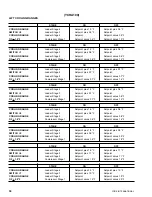
Page 30 shows a listing of each cooling range code
along with the temperatures at which each stage loads
and unloads.
CODE
RANGE
0
+ 1.0°F
1
+ 1.2°F
2
+1.4°F
3
+1.5°F
4
+1.6°F
5
+1.8°F
6
+1.9°F
7
+2.0°F
LOADING/UNLOADING
[RETURN WATER TEMPERATURE (RWT)
CONTROL – STANDARD]
Loading/Unloading of cylinders is accomplished in re-
sponse to return chilled water temperature as sensed
by the Micro Logic Board. Cooling Ranges from 6 to
14°F can be selected to control loading/unloading. A
typical example is illustrated below.
RWT Setpoint = 55°F
Cooling Range = 10°
System Switch = ON
J10 on Micro Logic = OUT
or
Sw. 3 on Micro = OFF
RWT CONTROL
Return Water
Temp. °F
55 --------------------
---------
Loader ON Stage 4 -----------------------
-------------------------------------
Cooling
52.5 ------------------
---------
Loader ON Stage 3 -----------------------
– Loader OFF Stage 4
Range
50.0 ------------------
---------
Loader ON Stage 2 -----------------------
– Loader OFF Stage 3
*10°F
47.5 ------------------
---------
Compressor ON (Unloaded) Stage 1
– Loader OFF Stage 2
45 --------------------
---------
Compressor OFF --------------------------
– Compressor OFF Stage 1
*10°F
÷
4 stages = 2.5°F between stages of loading.
Temperature
Fall
Temperature
Rise
➤
➤
Summary of Contents for YCAQ10
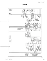
Page 20: ...YORK INTERNATIONAL 20 LD01779 YCHA100 FIG 9 WIRING DIAGRAM YCHA100...
Page 21: ...FORM 150 40 NM20 21 YORK INTERNATIONAL YCHA100 LD01779 D...
Page 22: ...YORK INTERNATIONAL 22 LD01780 L YCHA100 FIG 9 Continued...
Page 23: ...FORM 150 40 NM20 23 YORK INTERNATIONAL LD01780 R YCHA100...
Page 24: ...YORK INTERNATIONAL 24 YCHA100 LD01781 FIG 9 Continued...
Page 25: ...FORM 150 40 NM20 25 YORK INTERNATIONAL LD01782 YCHA100...
Page 46: ...YORK INTERNATIONAL 46 LD01787...
Page 47: ...FORM 150 40 NM20 47 YORK INTERNATIONAL LD01788...
Page 48: ...YORK INTERNATIONAL 48 LD01789...
Page 49: ...FORM 150 40 NM20 49 YORK INTERNATIONAL LD01790...
Page 50: ...YORK INTERNATIONAL 50 LD01791...
Page 51: ...FORM 150 40 NM20 51 YORK INTERNATIONAL LD01792...
Page 77: ......
Page 78: ......
Page 79: ......
Page 80: ......
Page 81: ......
Page 82: ......
Page 83: ......
Page 84: ......
Page 85: ......
Page 86: ......
Page 87: ......
Page 88: ......
Page 89: ......
Page 90: ......
Page 91: ......
Page 92: ......
Page 93: ......
Page 94: ......
Page 95: ......
Page 96: ......
Page 97: ......
Page 98: ......
Page 99: ......


