Proud Sponsor
of the 1998
U.S. Olympic Team
36USC380
P.O. Box 1592, York, Pennsylvania USA 17405-1592
Subject to change without notice. Printed in USA
Copyright © by York International Corporation 1997
ALL RIGHTS RESERVED
Form 150.40-NM20 (597)
Supersedes: 150.40-NM20 (587)
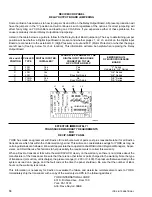
SMART PANEL EQUIPPED
LCH & YCHA RECIPROCATING CHILLERS
MIS-DIAGNOSING INCORRECT SERVICE VALVE
POSITIONING AS TRANSDUCER FAILURES
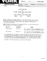
Recently we have been made aware that transducers mounted on Service valves have been sometimes mistakenly
diagnosed as being defective. It was later found that the transducer’s output was wrong because the transducer had
been valved off due to incorrect Service valve positioning.
Be sure, after replacing a transducer or when starting a new chiller where the Service valves have been placed in the
front-seat position to close off the system, that you back-seat all Service valves completely and then turn them one
turn toward the front seat position to assure that the transducers are not valved off. This should also be checked
when troubleshooting. In the past, we have found the customer’s maintenance people have occasionally valved off
transducers by mistake.
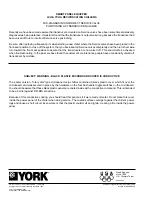
SUBJECT: WARNING - BLACK PLASTIC MICROBOARD COVER IS CONDUCTIVE
The earlier version, “rotary dial” type micropanel recip chillers contained a black plastic cover which fit over the
microboard, and was secured in place by the hardware on the four bat-handle toggle switches on the microboard.
You should be aware that these black plastic panels are coated inside with a conductive compound. This is intended
to be a barrier against RFI-EMI emissions.
Because of this conductive coating, you should treat this panel as if it were made of metal. Do not place this cover
inside the power panel of the chiller when doing service. The coated surface could get against the chiller’s power
lugs and cause a short circuit. Even worse is that the plastic could melt and ignite, creating a fire inside the power
panel.
Summary of Contents for YCAQ10
Page 20: ...YORK INTERNATIONAL 20 LD01779 YCHA100 FIG 9 WIRING DIAGRAM YCHA100...
Page 21: ...FORM 150 40 NM20 21 YORK INTERNATIONAL YCHA100 LD01779 D...
Page 22: ...YORK INTERNATIONAL 22 LD01780 L YCHA100 FIG 9 Continued...
Page 23: ...FORM 150 40 NM20 23 YORK INTERNATIONAL LD01780 R YCHA100...
Page 24: ...YORK INTERNATIONAL 24 YCHA100 LD01781 FIG 9 Continued...
Page 25: ...FORM 150 40 NM20 25 YORK INTERNATIONAL LD01782 YCHA100...
Page 46: ...YORK INTERNATIONAL 46 LD01787...
Page 47: ...FORM 150 40 NM20 47 YORK INTERNATIONAL LD01788...
Page 48: ...YORK INTERNATIONAL 48 LD01789...
Page 49: ...FORM 150 40 NM20 49 YORK INTERNATIONAL LD01790...
Page 50: ...YORK INTERNATIONAL 50 LD01791...
Page 51: ...FORM 150 40 NM20 51 YORK INTERNATIONAL LD01792...
Page 77: ......
Page 78: ......
Page 79: ......
Page 80: ......
Page 81: ......
Page 82: ......
Page 83: ......
Page 84: ......
Page 85: ......
Page 86: ......
Page 87: ......
Page 88: ......
Page 89: ......
Page 90: ......
Page 91: ......
Page 92: ......
Page 93: ......
Page 94: ......
Page 95: ......
Page 96: ......
Page 97: ......
Page 98: ......
Page 99: ......

