137
YORK INTERNATIONAL
FORM 201.19-NM6 (804)
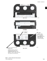
I/O Expansion Board #1
The I/O Expansion Board provides multiplexing to al low
additional inputs to be connected to the Mi cro pro ces sor
Board via a sin gle data line. The additional in puts are
multiplexed ac cord ing to the selection made by the
Mi cro pro ces sor through address lines.
Signals routed through the I/O Expansion Board in clude
Dis charge Temperature, Motor Protector, Current Trans-
former outputs (motor current signals from the 2ACE
module), and Oil Temperature.
Included on the I/O Expansion Board are the outputs for
the slide valve control. This control consists of a Digital
to Analog Converter (DAC) and power tran sis tors to
modulate current through the slide valve so le noids.
I/O Expansion Board # 2
The second I/O Expansion Board is used only on 3 and
4 compressor YCAS chillers. Due to limited output and
input capabilities of the main Microprocessor Board, an
additional Microprocessor is needed to control a third
and fourth compressor.
The second I/O Expansion Board has processing capa-
bilities. It’s job is to monitor inputs from the third and
fourth com pres sor, provide safety control, and shut tle
in for ma tion back to the main Microprocessor Board.
The shuttling of information is done using an RS-485
com mu ni ca tion line to the Microprocessor Board.
Communication between the Microprocessor Board
and I/O Board #2 takes place approximately once ev-
ery sec ond. The communications transfer is necessary
to en able the main Microprocessor to display system
pa ram e ters and command the starting, stopping, load-
ing, and unloading of System 3 and 4 to control chilled
liquid temperature.
The second I/O Expansion Board also controls the
out puts to a Relay Output Board which activates and
de-activates 115VAC control outputs to System 3 and 4
com pres sors, solenoids, etc. These outputs are con trolled
in re sponse to commands issued by the Mi cro pro ces sor
Board.
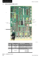
Relay Output Boards
One Relay Output Board per system operates the mo tor
contactors/starters, solenoid valves, and heaters which
control system operation.
The relay boards are located in the logic section of
the control panel(s). The boards convert 0 - 12VDC
logic lev els outputs from the Microprocessor Board to
115VAC lev els used by the contactors, valves, etc.
The common side of all relays on the Relay Output
Board is connected to +12VDC REG. The open col lec tor
out puts of the Microprocessor Board energize the DC
re lays or triacs by pulling the other side of the relay
coil/triac to 0VDC. When not energized, both sides of
the relay coils or triacs will be at +12VDC potential.
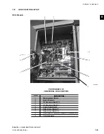
1.6 CIRCUIT
BREAKERS
Circuit Breakers are provided for the 115VAC con-
trols.
• CB1, CB2, and CB3 allows removal of control pow er
from respective System 1, 2, or 3 for control sys tem
cir cuit ry ser vic ing. Spe cifi cal ly, the 115VAC feed to
Relay Out put Board 1 which en er giz es contactors
and so le noids.
• CB4 allows removal of control power to the Mi-
cro pro ces sor Board, Power Supply Board, I/O Ex-
pan sion Boards, and Evaporator Heater on 3 Sys tem
chillers.
• CB5 allows removal of control power to the Mi-
cro pro ces sor Board, Power Supply Board, I/O Ex-
pan sion Board, and Evap o ra tor Heater on 4 Sys tem
chillers.
The Circuit Breakers remove 115VAC
control power only. High voltage cir-
cuit ry will still be en er gized from the
high volt age supply.
REMOVING 115VAC power to or
open ing CB4 (3 System chillers) or
CB5 (4 System chillers), re moves
pow er from the evap o ra tor heat ers.
This could cause evap o ra tor freeze-
up in low ambient tem per a tures.
Removing 115VAC power to individual
circuits also removes power to the
compressor heaters, which should
also be avoided.
8
Summary of Contents for YCAS
Page 43: ...43 YORK INTERNATIONAL FORM 201 19 NM6 804 5 This page intentionally left blank...
Page 45: ...45 YORK INTERNATIONAL FORM 201 19 NM6 804 6 This page intentionally left blank...
Page 65: ...65 YORK INTERNATIONAL FORM 201 19 NM6 804 7 LD09359 Electronic Panel 035 19205 104 Rev A...
Page 81: ...81 YORK INTERNATIONAL FORM 201 19 NM6 804 LD09378 CONNECTION WIRING DIAGRAM Electronic Panel...
Page 91: ...91 YORK INTERNATIONAL FORM 201 19 NM6 804 This page intentionally left blank...
Page 147: ...147 YORK INTERNATIONAL FORM 201 19 NM6 804 8 This page intentionally left blank...
Page 205: ...205 YORK INTERNATIONAL FORM 201 19 NM6 804 8 This page intentionally left blank...

