180
YORK INTERNATIONAL
FORM 201.19-NM6 (804)
Low Leaving Liquid Temperature CutOut
The Low Leaving Liquid Temperature Cutout protects
the evaporator from damage due to ice build up caused
by operation below the chilled liquid freezing point.
If the leaving chilled liquid temperature (water or gly col)
drops below the cutout point, the chiller will shut down.
The chiller will restart automatically when tem per a ture
rises more than 4°F (2°C) above the cutout point and
cooling demand exists.
If the Dip Switch on the microprocessor board is set
for “Water Cooling” (see Section 3.7, page 158) the
cut out is automatically set at 36°F (2°C) and cannot be
re pro grammed. If the Switch is set for “Brine Cool ing”
(gly col) the cutout can be programmed between 08.0 -
36.0°F (-13 through -2°C). The cutout should normally
be set to 4°F (2°C) below the setpoint minus the range,
i.e. 34°F (setpoint) – 2°F (range) - 4°F = 28°F (see Sec-
tion 6, page 170).
To program the Leaving Liquid Temperature Cutout, key
in the required setting and press the Enter key to store the
value into memory and scroll to the next dis play.
High Motor Current Unload Point
The Motor Current Unload point is used to avoid a
high motor current safety shutdown by unloading a
com pres sor, if current draw approaches the maximum
limit cut out value. The chiller can then continue to run
au to mat i cal ly at reduced capacity until the cause of the
ex ces sive current is attended to.
The micro will accept between 30 - 105% for the un load
point. The motor current safety will shut the com pres sor
down whenever current exceeds 115%.
If the programmable limit is set between 100% and
105% of full load current, this feature will protect
against ex ces sive current causing compressor shutdown
due to extremely high ambient, high chilled liquid tem-
per a ture, and condenser malfunction caused by dirt or
fan prob lems.
If the programmable limit is set below 100% of full load
current, this control feature can be used for “demand
lim it ing”. This is important when demand limiting is
crit i cal due to power requirements or limitations in the
build ing (See also Section 1.10).
To program the Suction Pressure Cutout, key in the re-
quired setting and press the Enter key to store the value
into memory and scroll the next display.
High Ambient Temperature Cutout
The High Ambient Cutout is used to select the ambient
temperature above which the chiller may not operate.
If the ambient temperature rises 1°F (.5°C) above this
point, the chiller will shut down. Restart will occur au-
to mat i cal ly, when temperature falls more than 2°F (1°C)
below the cutout and cooling demand is present.
This cutout is normally set at 130°F (54°C) to allow op-
eration to the absolute maximum temperature ca pa bil i ty
of the electromechanical components; however, values
between 100.0 - 130.0°F (38 - 54°C) are ac cept ed.
To program the High Ambient Cutout, key in the re-
quired setting and press the Enter key to store the value
into memory and scroll to the next display.
Low Ambient Temperature Cutout
The Low Ambient Cutout is used to select the ambient
temperature below which the chiller may not operate.
If the ambient temperature falls 1°F (.5°C) below this
point, the chiller will shut down. Restart will occur
au to mat i cal ly, when temperature rises more than 2°F
(2ºC) above the cutout and cooling demand is present
(see also Section 2.5 page 151).
If the SW1 Dip Switch on the Microprocessor Board
is set for “Standard Ambient Control” (see Section
3.7) the low ambient cutout is set at 25°F (-4°C) and is
NOT programmable. If the Dip Switch is set for “Low
Am bi ent Control”, programming of the cutout be tween
00.0 - 50.0°F (-17.8 - 10°C) is allowed. This al lows
higher val ues than 25°F (-4°C) to be pro grammed to
shut down the chiller when other cooling methods
become op er a tion al. Values below 25°F (-4°C) can
be used for ap pli ca tions requiring chiller operation at
low er tem per a tures. The chiller will not operate below
0ºF (-17.8ºC).
To program the Low Ambient Cutout, key in the re quired
setting and press the Enter key to store the value into
memory and scroll to the next display.
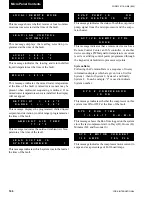
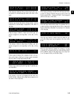
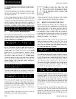
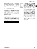
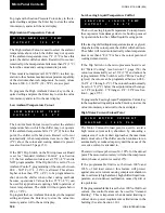
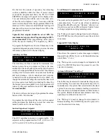
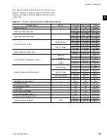
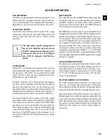
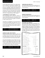
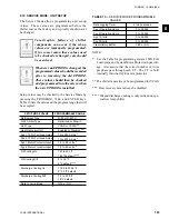
H I G H A M B I E N T T E M P
C U T O U T = 1 3 0 . 0 ° F
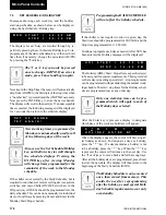
L O W A M B I E N T T E M P
C U T O U T = 2 5 . 0 ° F
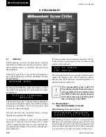
L E A V I N G L I Q U I D T E M P
C U T O U T = 3 6 . 0 ° F
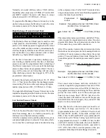
H I G H M O T O R C U R R E N T
U N L O A D = 1 0 5 % F L A
Micro Panel Contents
Summary of Contents for YCAS
Page 43: ...43 YORK INTERNATIONAL FORM 201 19 NM6 804 5 This page intentionally left blank...
Page 45: ...45 YORK INTERNATIONAL FORM 201 19 NM6 804 6 This page intentionally left blank...
Page 65: ...65 YORK INTERNATIONAL FORM 201 19 NM6 804 7 LD09359 Electronic Panel 035 19205 104 Rev A...
Page 81: ...81 YORK INTERNATIONAL FORM 201 19 NM6 804 LD09378 CONNECTION WIRING DIAGRAM Electronic Panel...
Page 91: ...91 YORK INTERNATIONAL FORM 201 19 NM6 804 This page intentionally left blank...
Page 147: ...147 YORK INTERNATIONAL FORM 201 19 NM6 804 8 This page intentionally left blank...
Page 205: ...205 YORK INTERNATIONAL FORM 201 19 NM6 804 8 This page intentionally left blank...

