29
YORK INTERNATIONAL
FORM 201.19-NM6 (804)
VIBRATION ISOLATORS
Optional sets of vibration isolators can be supplied loose
with each unit.
Using the Isolator tables, refer to the
Technical Data
Section
, identify each mount and its cor rect lo ca tion
on the unit.
Installation
Place each mount in its correct position and lower the
unit carefully onto the mounts ensuring the mount en-
gag es in the mounting holes in the unit base frame.
On adjustable mounts, transfer the unit weight evenly to
the springs by turn ing the mount adjusting nuts (lo cat ed
just be low the top plate of the mount) counter-clock wise
to raise and clock wise to low er. This should be done
two turns at a time until the top plates of all mounts are
between 1/4" and 1/2" (6 and 12 mm) clear of top of
their hous ing and the unit base is level.
A more detailed installation in struc tion
is pro vid ed in the Installation Instruc-
tions for VMC Series AWR/AWMR and
CP Restrained Mountings Section of
this manual, (page 119).
SHIPPING BRACES
The chiller’s modular design does not require shipping
braces.
PIPEWORK CONNECTION
General Requirements
The following piping recommendations are intended
to ensure satisfactory operation of the unit(s). Failure
to follow these rec om men da tions could cause damage
to the unit, or loss of per for mance, and may in val i date
the warranty.
The maximum fl ow rate and pressure
drop for the evaporator must not be
ex ceed ed at any time. Re fer to the
Tech ni cal Data Sec tion for de tails.
The liquid must enter the evaporator
at the in let con nec tion. The inlet con-
nec tion for the evaporator is at the
control panel end of the unit when
viewed from the pow er and con trol
pan els.
The water inlet is always at the end
of the evaporator where the liquid
refrigerant enters and the suction
gas leaves.
A fl ow switch must be installed in the customer
pipework at the outlet of the evaporator and wired
back to the control panel using shielded ca ble.
There
should be a straight run of piping of at least 5 pipe di-
am e ters on either side. The fl ow switch should be wired
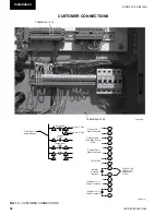
to Ter mi nals 13 and 14 (see Figs. 13 and 14, pages 38
and 39). A fl ow switch is re quired pre vent dam age to
the evaporator caused by the unit op er at ing with out
ad e quate liquid fl ow.
The fl ow switch used must have gold plated contacts
for low voltage/current operation. Paddle type fl ow
switch es suitable for 150 PSIG (10 bar) (optional 300
PSIG) working pres sure and hav ing a 1" N.P.T. con-
nection can be obtained from YORK as an ac ces so ry
for the unit. Al ter na tive ly a dif fer en tial pres sure switch
sited across an orifi ce plate may be used, pref er a bly of
the high/low limit type.
The chilled liquid pump(s) installed in the pipework
system(s) should discharge directly into the unit evapora-
tor section of the system. The pump(s) may be controlled
external to the unit - but an override must be wired to the
control panel so that the unit can start the pump in the
event that the liquid temperature falls below the min i mum
setting. For details refer to “Electrical Con nec tion.”
4
Summary of Contents for YCAS
Page 43: ...43 YORK INTERNATIONAL FORM 201 19 NM6 804 5 This page intentionally left blank...
Page 45: ...45 YORK INTERNATIONAL FORM 201 19 NM6 804 6 This page intentionally left blank...
Page 65: ...65 YORK INTERNATIONAL FORM 201 19 NM6 804 7 LD09359 Electronic Panel 035 19205 104 Rev A...
Page 81: ...81 YORK INTERNATIONAL FORM 201 19 NM6 804 LD09378 CONNECTION WIRING DIAGRAM Electronic Panel...
Page 91: ...91 YORK INTERNATIONAL FORM 201 19 NM6 804 This page intentionally left blank...
Page 147: ...147 YORK INTERNATIONAL FORM 201 19 NM6 804 8 This page intentionally left blank...
Page 205: ...205 YORK INTERNATIONAL FORM 201 19 NM6 804 8 This page intentionally left blank...

